Project Log: Sunday, January 2, 2011
With the greatest reluctance, yet a sense of
sigh-inducing inevitability, I made two important (and
related) decisions.
First, I would remove the caprails so that I could
properly rebed them (with the added benefit that removal
would make repairs and refinishing easier). I'd
been concerned about this for some time, given the
minimalist approach to sealant application that seemed
to be in effect at the Fisher factory when my boat was
built, but what pushed me over the edge and forced me to
make the decision I'd been postponing was an email from
another Fisher owner who highly recommended I do so,
based on his own experience.
I didn't want to remove the caprails--far from
it--but I just didn't see any other legitimate way
forward. Sigh. I could only hope they'd come
off effectively and in whole pieces.
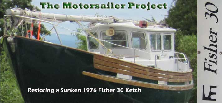
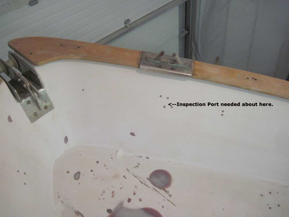
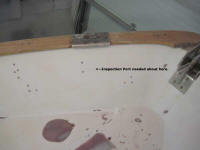
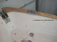
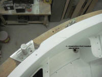
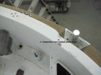
Second, in order to access the fasteners for the
still-installed forward chocks, after mooring bits, and
mizzen stay U-bolts, I had no choice but to commit to
cutting holes for and installing inspection ports in the
bulwarks and cockpit coamings. Even with the
interior of the boat gutted, there was not access to the
underside of these fasteners, but in order to rebed the
caprails, I'd have to remove these pieces of hardware,
along with the other U-bolts spread along the lengths of
the rails (and which were accessible from beneath).
I hated the thought of inspection ports, but didn't see
any viable alternative. |
 |
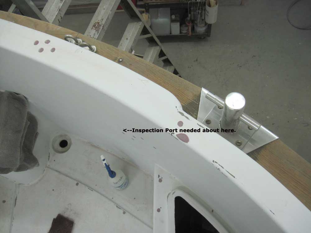
There was no way I was going to install those cheap,
weak, ugly, leaky, silicone sealant-requiring* plastic
inspection ports all over the boat. Therefore, I
spent some time looking for a reasonable alternative.
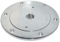
Eventually, I located some 4" inspection ports made from
316 alloy stainless steel that were available at an
acceptable price and which I could stand to have on the
boat. I liked the cover plates, which featured not
only the usual holes for a deck plate key, but also a
recess to accept a standard winch handle.
Although generally I'd tend to head straight for the
various bronze suppliers for hardware, I rejected bronze
inspection ports from the beginning. The existing
hardware on this boat was either stainless steel or
chromed bronze, and somehow that look seemed to suit the
boat. Therefore, I planned to remain as consistent
as possible in my hardware choices going forward.
I ordered the inspection ports so I could have them on
hand in order to drill the proper-sized holes for their
installation. |
 |
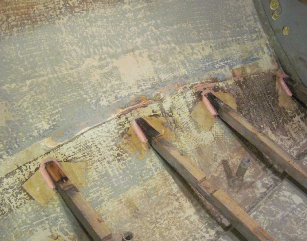
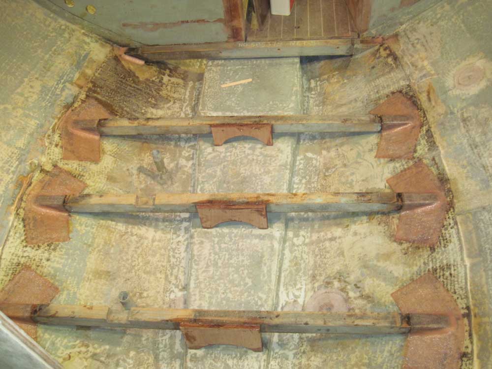
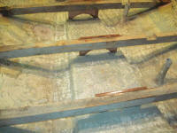
I continued work on the cabin sole support beams.
After lightly sanding the cured adhesive I'd used to
secure the beams to the hull, as well as the hull
immediately adjacent to the beams, I vacuumed and
solvent-washed, then installed wide thickened epoxy
fillets around the ends of the beams, these to aid in
the overall strength of the connection as well as to
provide smooth radii for the fiberglass cloth to lie
across. |


 |
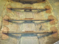
With the beams secured to the hull on each side, I'd
already noticed a vast improvement in their overall
stiffness, since the ends of the beams could no longer
slide around when weight was applied to their centers.
However, I still felt that a center support structure
would be worthy in the end.
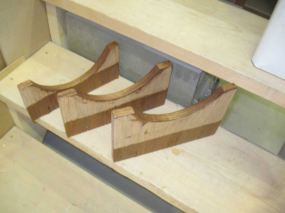
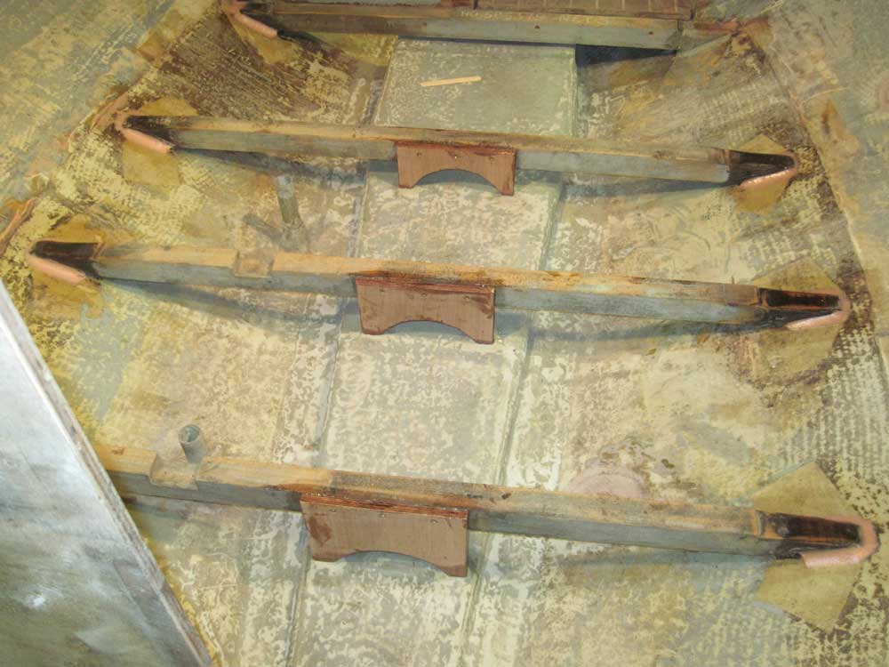
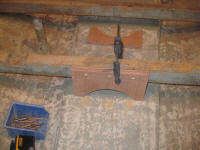
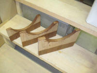
From 18mm Meranti plywood, I built three supports--one
for each beam. Each support was a basic rectangle,
sized according to the specific height of its respective
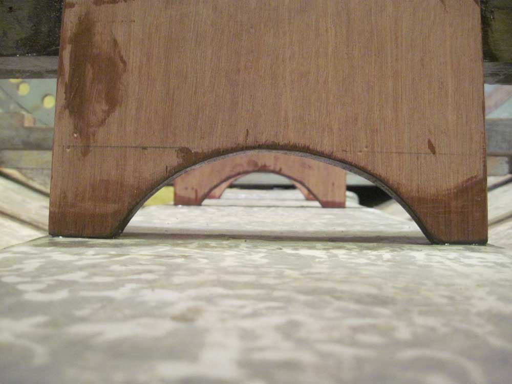
beam above the bilge. Into the bottom of each
basic rectangle I cut a large arched opening, leaving
two "feet" that would carry the weight of the cabin sole
above while leaving plenty of room for water drainage
and cleaning, etc.
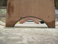
To install the supports, I first clamped each one in
place and drilled and counterbored for three bronze
screws in each support. |
 |
Next, I coated part the back surface of the plywood,
along with the bottom of the arch and the feet, with
epoxy resin and set the pieces aside for a while to
partially cure while I worked on other things. I
left portions uncoated for now so that I could work with
the uncured pieces, but later I'd coat all surfaces with
epoxy as a safeguard against moisture. |
 |
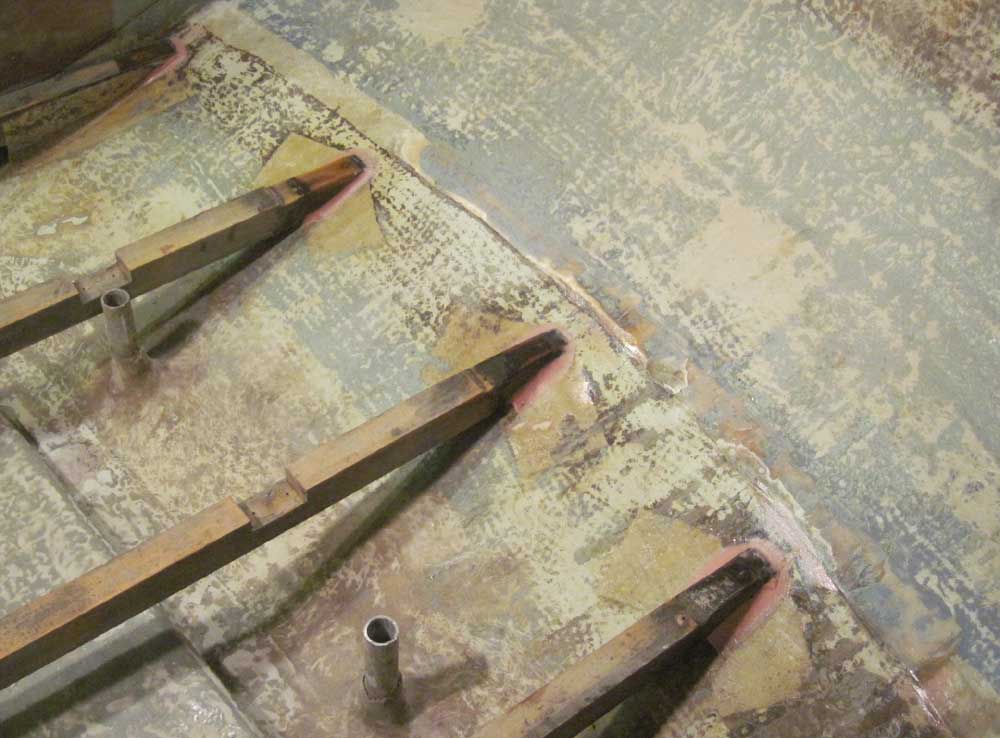
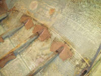
I installed the centerline supports with epoxy adhesive
applied to the back of the plywood, where it rested
against the beam, and to the bottoms of the "feet" that
would rest on the top of the raised ballast bulge in the
bilge. Earlier, during the test-fitting of the
supports, I'd marked the locations of these feet, and
then ground the gelcoated surface of the bilge to accept
the adhesive.
With the adhesive applied, I secured each piece to the
beam with three bronze 2" screws. |
 |
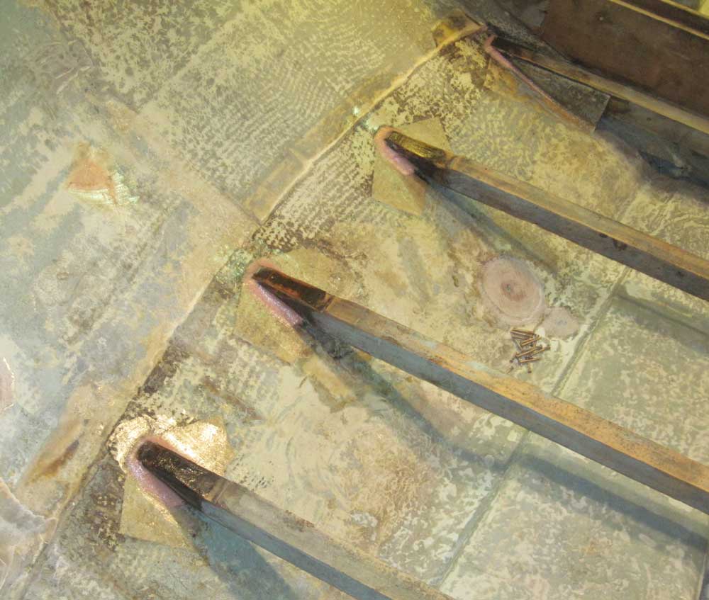
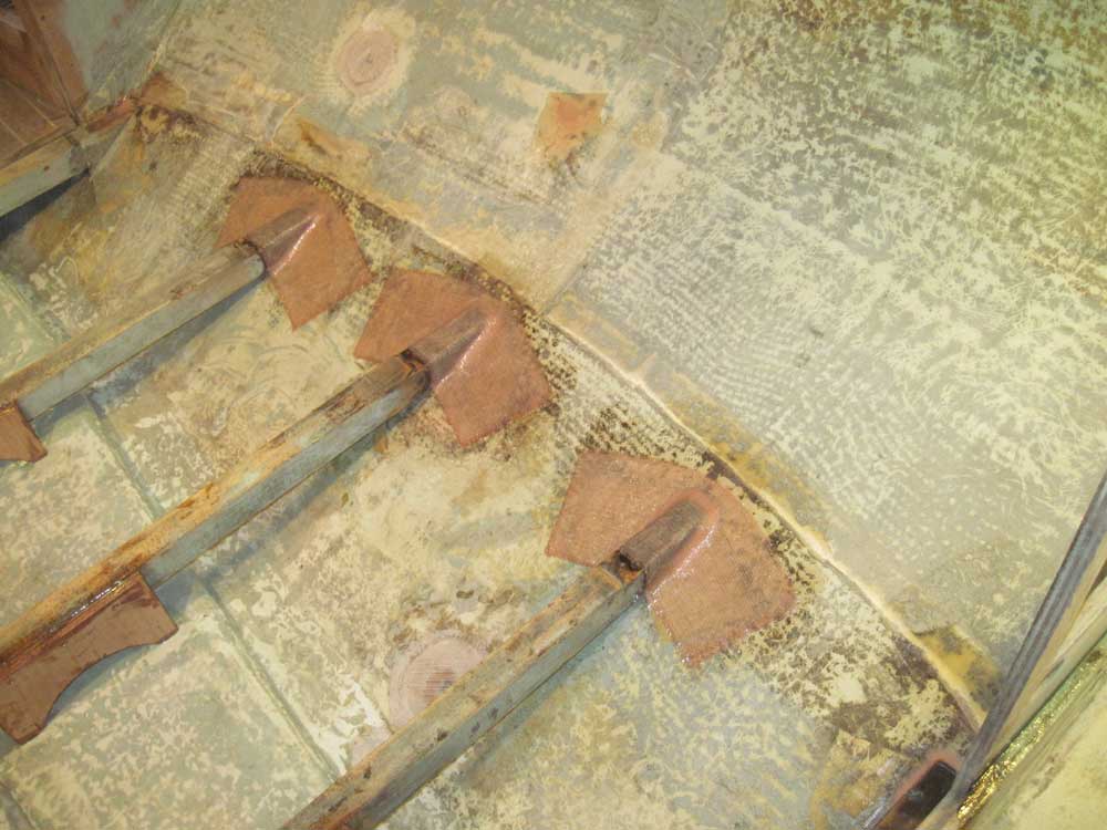
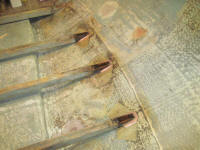
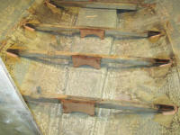
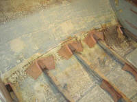
By now, the epoxy fillets had set up enough to continue
work on the beam ends. I prepared six pieces of 6"
wide biaxial tabbing and installed the tabbing over the
beam ends and onto the hull. Note that the ends of
the beams featured a recessed area (from the factory)
that would allow the tabbing to remain below the top of
the beam itself, so that the plywood cabin sole could
extend across without interference.
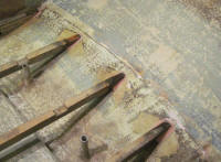
I extended the tabbing well onto the hull on each side,
as well as slightly above the ends of the beams for best
adhesion and to seal off the beam ends; the original
tabbing installation had left the beam ends exposed,
which was less strong and subject to moisture damage. |

|
*Those familiar with my past work
already know my feelings on silicone sealant. For
those of you who may not know, here is my silicone
mantra: Silicone is pure evil.
|
Total Time Today: 3.5 hours
|
<
Previous |
Next > |
|
|