Project Log: Saturday, April 5, 2014
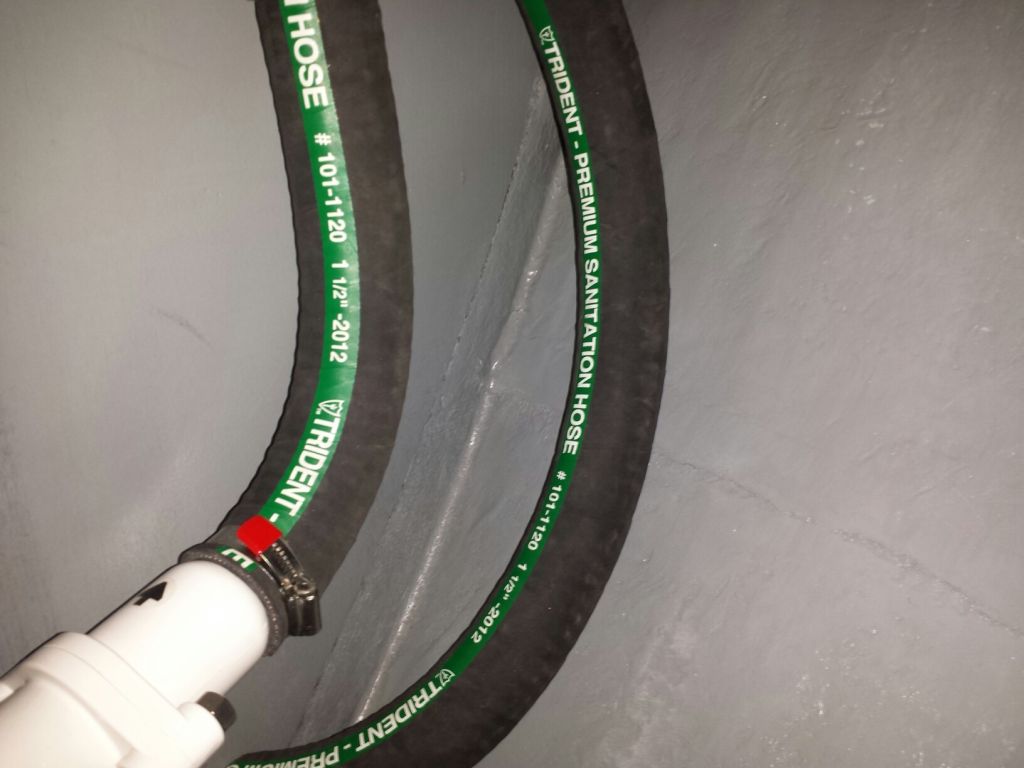
First on my agenda was to finish up the plumbing related
to the waste treatment system. Armed with a new
vented loop (siphon break), I worked in the wide-open,
yet awkward, space just outboard of the tank to install
the loop and final hose connections thereunto.
Reaching through the opening and beneath the platform to
the bulkhead beyond was just a twisting combination that
human arms were not quite meant to easily make, and I
couldn't see/reach well enough to get a screw in the far
outboard side of the vented loop. Otherwise, the
installation was straightforward, thanks to the nice
hose that actually had a bend radius, and actually fit
the barbs. The top of the vented loop was close to
the underside of the v-berth platform, which was above
the waterline.
|

 |
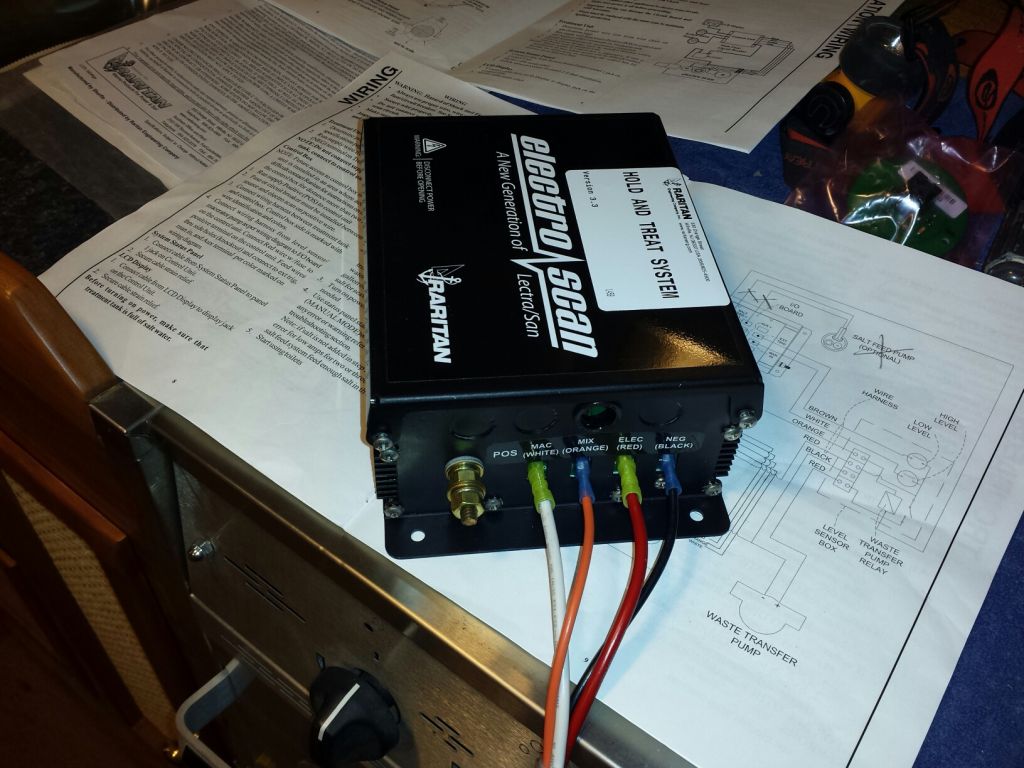
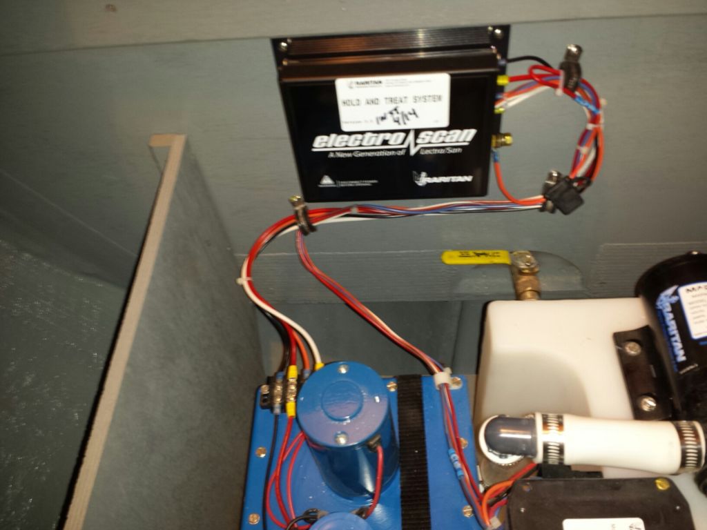
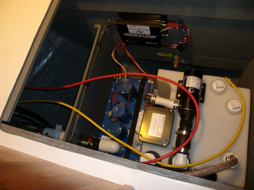
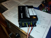
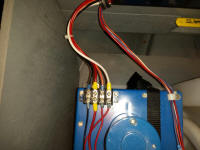
That completed the plumbing work, so I turned next to
the electrical side of the system, beginning with the
main control box. Two supplied wiring harnesses
needed to be connected to this box to operate the
system, and after a few reads through the instructions
and wiring schematics, it turned out to be
straightforward.
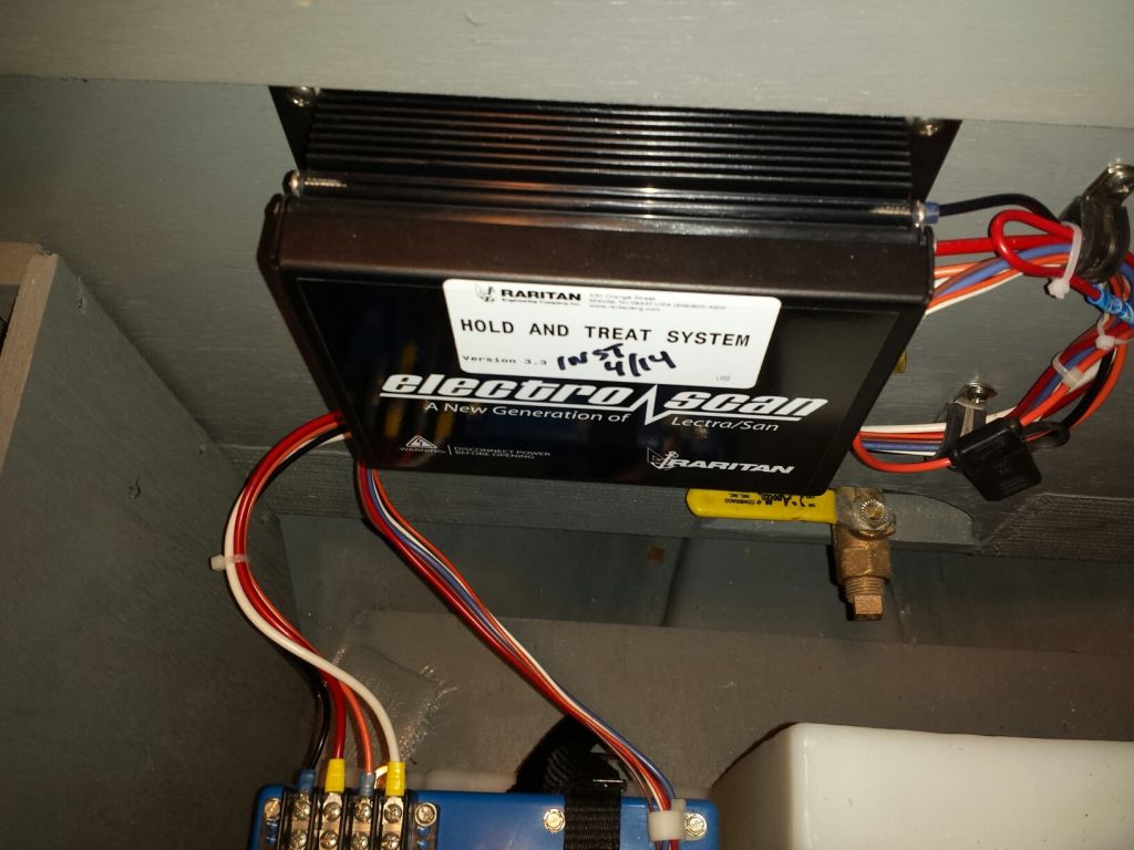
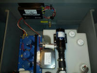
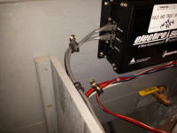
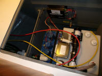
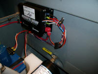
I mounted the box on the bulkhead just forward of the
tank, where it was easily accessible, protected, and
well within the 24" reach of the wiring harnesses.
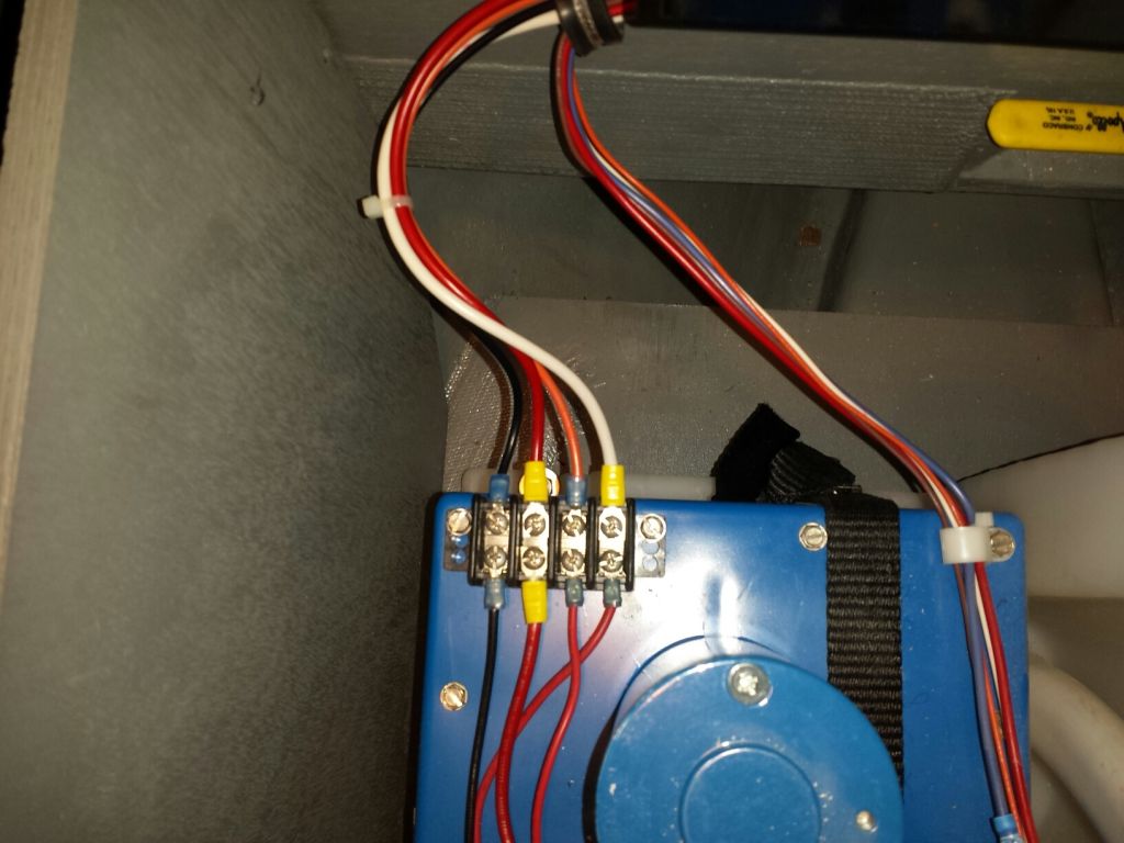
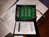
I connected the wires in their appropriate places, as
directed, and secured the harnesses with a few wire
clamps. One wiring harness led to the treatment
plant, the other to the tank's macerator pump and
high/low switch relay, which ultimately determined when
effluent would move from the tank to the treatment plant
and then overboard. |


 |
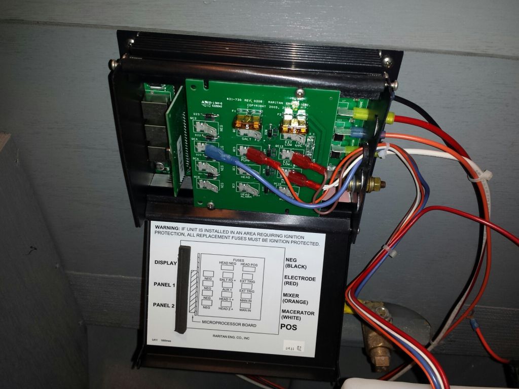
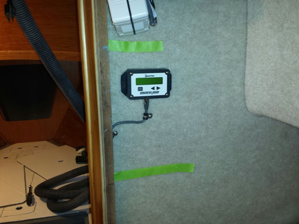
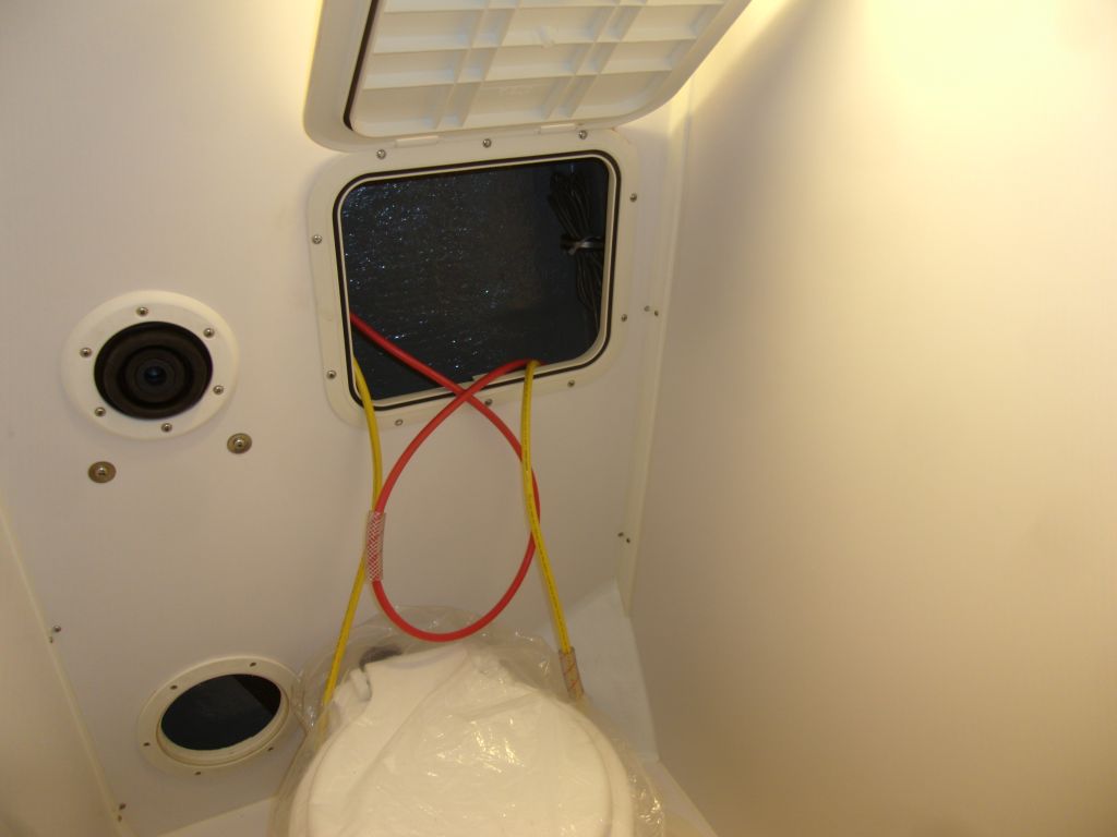
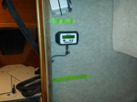
An LCD display, where overall functions could be
programmed, as well as a control panel were included,
and needed to be connected to the control box with
network cables. Only the small round control panel
needed to be accessible from the head itself, so to
limit water exposure I chose to install the LCD
programming display across the way in the hanging
locker, where it was easily accessible for programming,
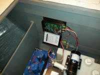
but otherwise out of the way. Before mounting the
box, I measured out for a couple future shelf locations,
so I could place the box appropriately between them.
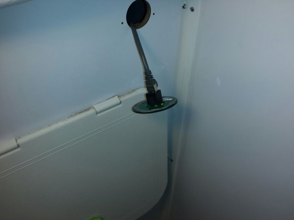
I led the network cable down the inside of the locker to
a point beneath the v-berth platform, then into the
forward compartment, where I ultimately connected the
other end to the control box. |
 |
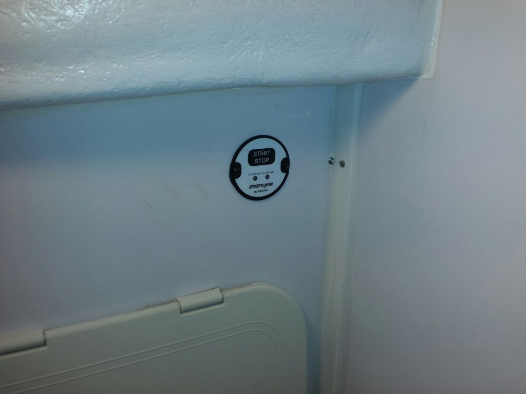
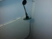
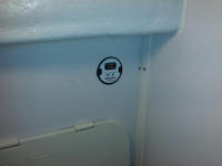
In the head, in a sheltered, out-of-the-way area, I
installed the small control panel, and led its own cable
to the control box forward. I applied sealant
beneath the control panel. |
 |
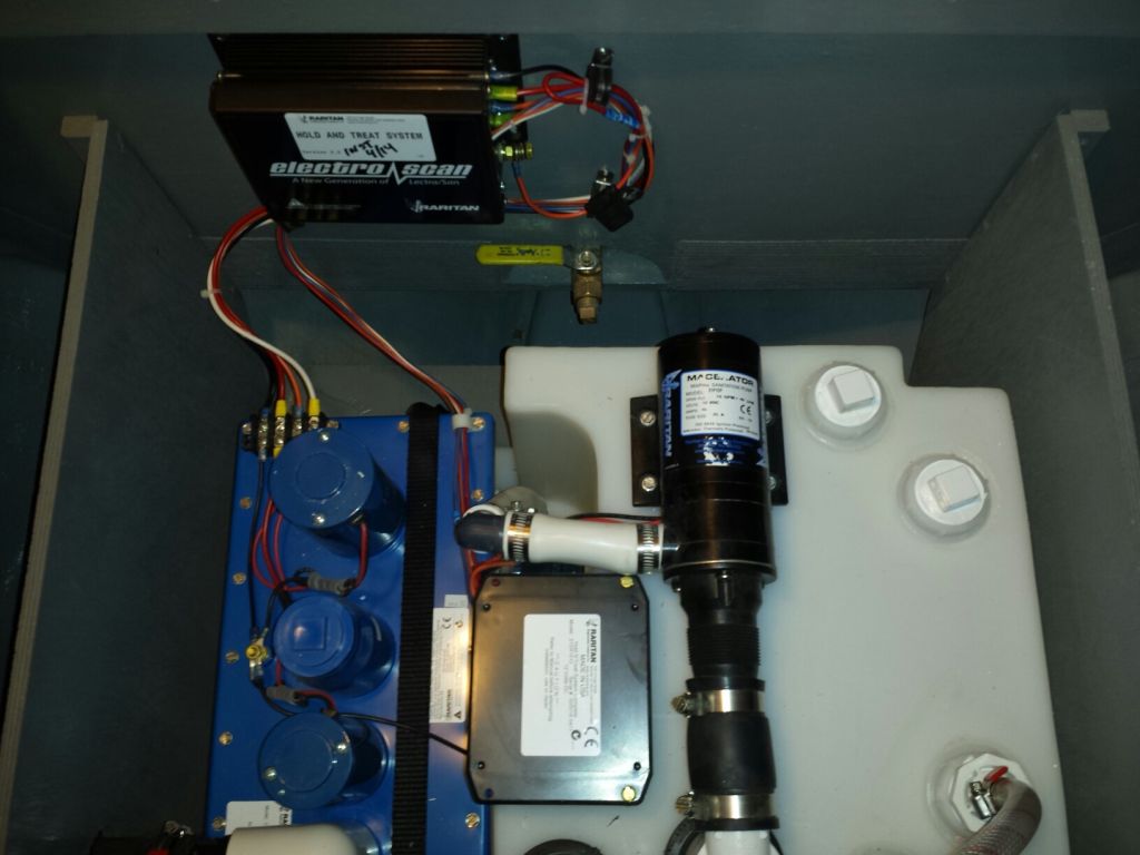
The treatment plant worked using electricity and salt
water somehow--I neither knew nor cared exactly how--and
would use significant amounts of power during
short-duration treatment cycles. During my bulk
wiring phase some time back, along with various other
wires I'd led a normal 14/2 conductor forward for the
sanitation system, apparently thinking mainly of power
to the macerator pump, not the high-amperage draw
required for the treatment plant; it never crossed my
mind that I might need larger cables, mainly since the
treatment plant, at that time, was simply a vague future
concept rather than an immediate reality, and I thought
I was planning appropriately ahead.
So in the event, I found myself now without the proper
conductors to operate the treatment plant. The
specifications called for at least 6AWG cable for the
distance I had to run. Fortunately, I happened to
have a supply of 4AWG cable on hand that I'd erroneously
ordered for another job a while back, and this larger
size would easily suit the amperage-carrying
requirements of the system.
Getting the new cables up to the bow was the hard part.
I gave this a lot of thought. The starboard side,
where I'd led most of the forward-leading cables
earlier, was too long and too convoluted a run for these
big cables, and even if I could have run them easily
that way, I couldn't face the prospect of it. I
didn't want to lead them through the bilge, though that
offered the most direct route. So ultimately, I
ended up running the two new cables (+/-) through the
upper port lockers, where I'd run other wires earlier.
This had the advantage of being easily accessible,
relatively straightforward, and close to the console and
electrical service.
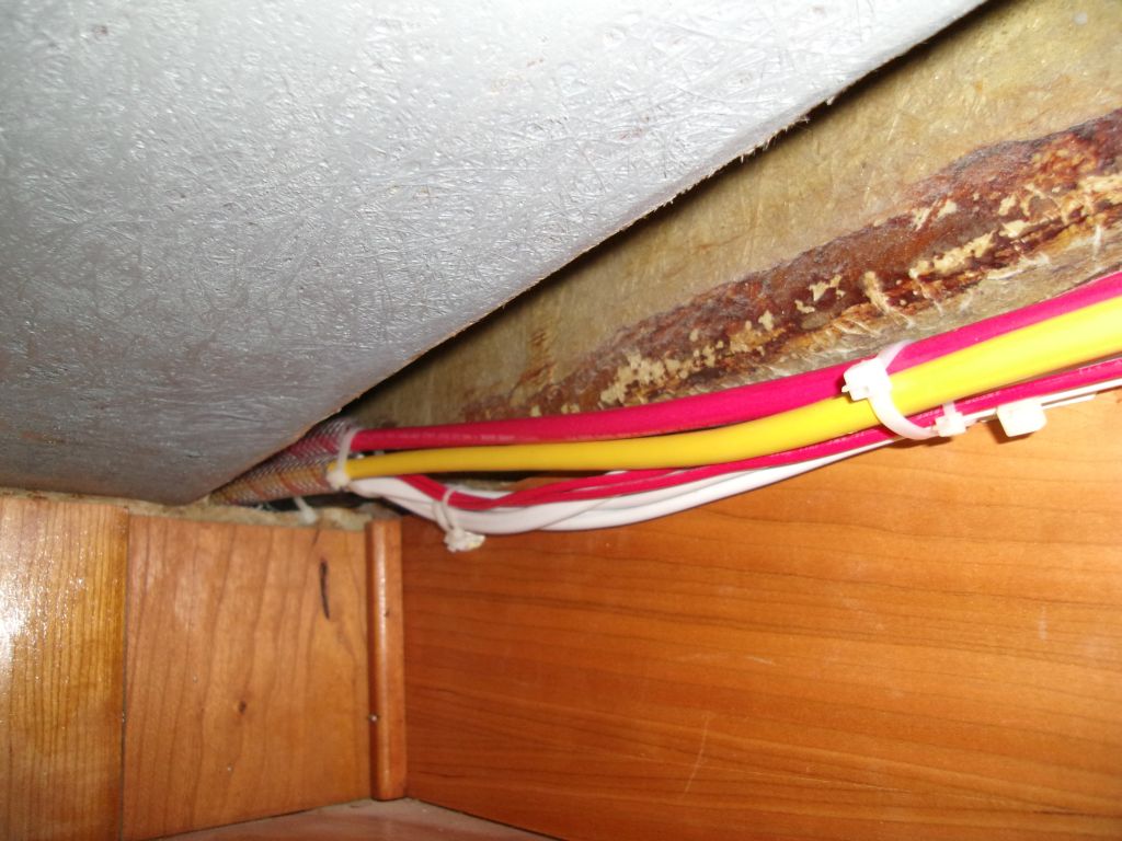
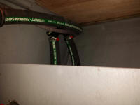
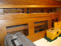
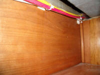
I led the cables through these spaces, from the port
tankage utility space in the pilothouse, above the
dinette, through the locker outboard of the head, and
finally into the utility space below the v-berth,
providing chafe protection at each bulkhead, divider, or
obstruction along the way. |

 |
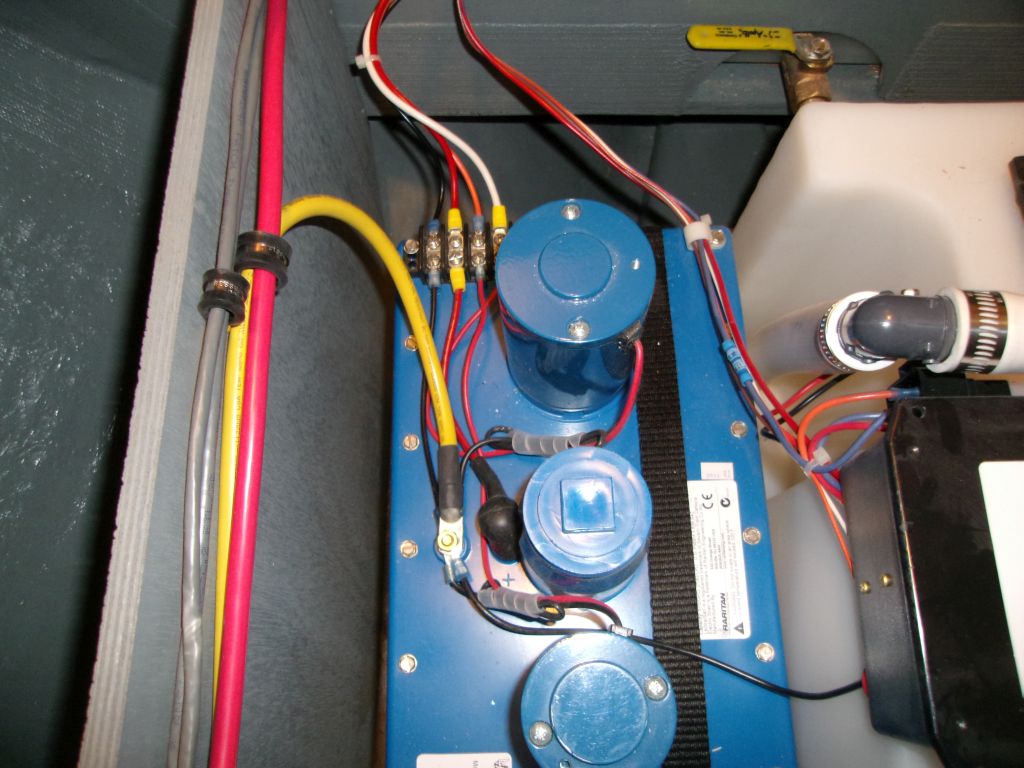
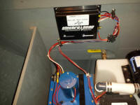
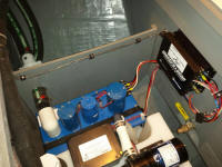
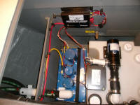
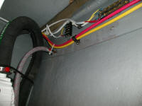
Once I had the cables snaked through the boat, I made up
the connections required at the sanitation system, to
the control box and the system ground. |

 |
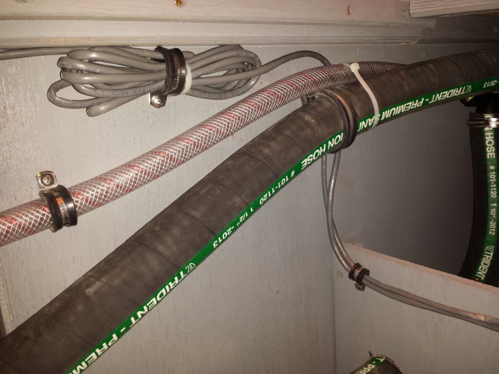
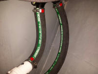
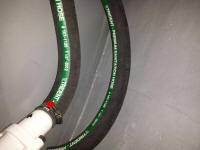
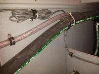
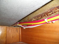
Then, working my way aft, I secured the cables and
removed slack, through one locker after another, and
slid the chafe-protecting lengths of hose (which I'd
threaded onto the cables as I'd led them forward) into
their final positions as needed. |
 |
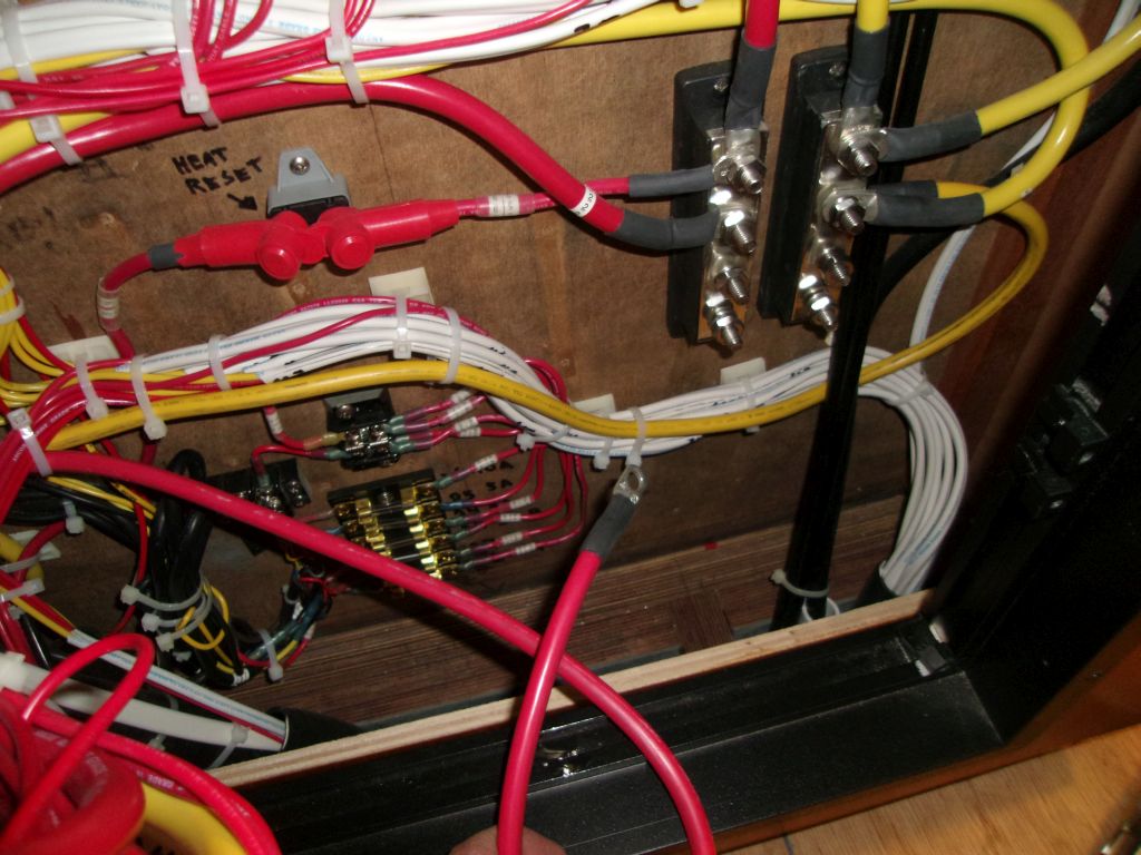
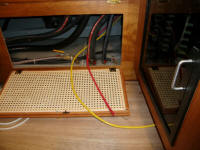
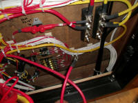
Finally, I led the two cables into the wiring
compartment in the console, and made up the ends.
I needed to get a larger circuit breaker for the panel,
so for the moment I left the red cable unattached, but
made up the yellow cable to one of the negative
distribution busses nearby. |
 |
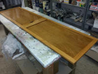
Finally, I had time for a fourth coat of gloss varnish
on the head door (back side). |
 |
| |
Total Time Today: 5.75 hours
|
<
Previous | Next > |
|
|