Project Log: Saturday, March 22, 2014
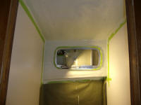
I lightly sanded the primer in the head compartment,
which had the desired effect of shearing off the
now-brittle fibers from the overhead. After
cleanup, I applied the first of several coats of
semi-gloss white enamel.
|
 |
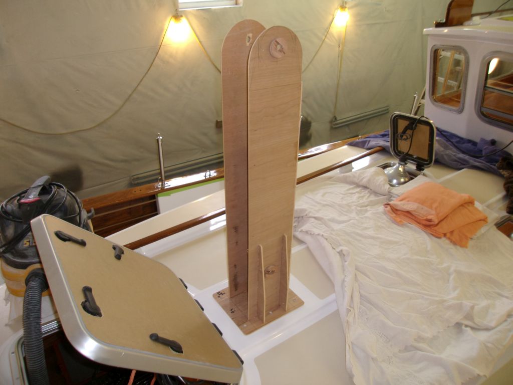
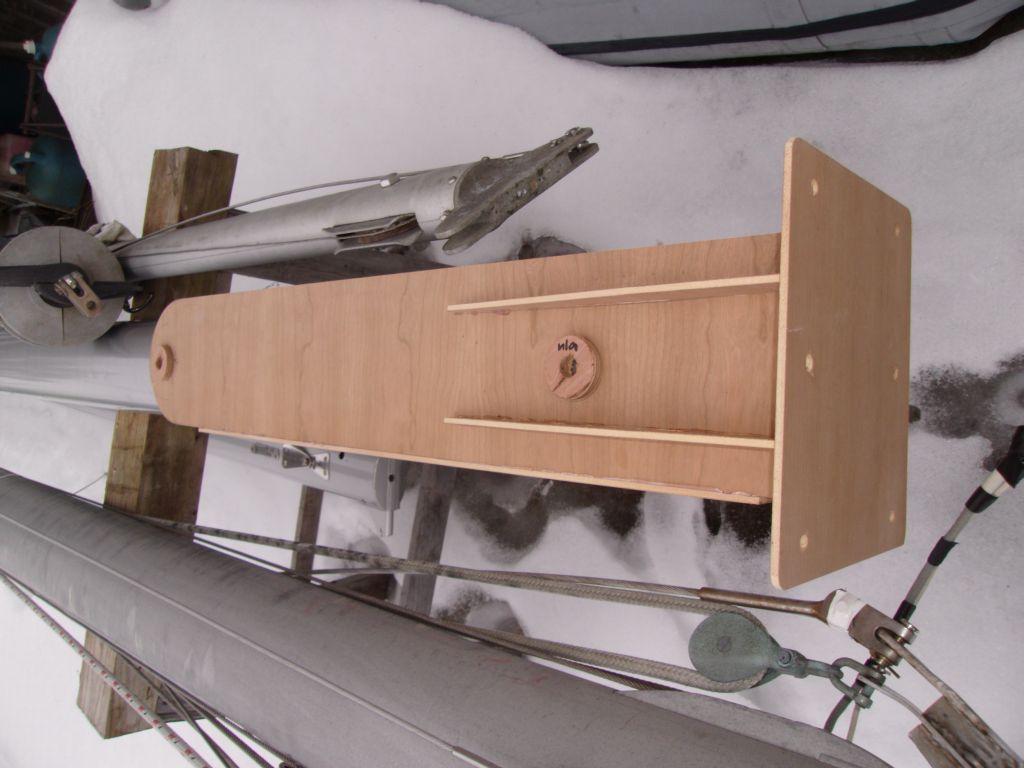
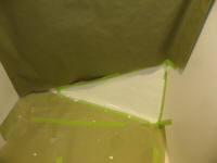
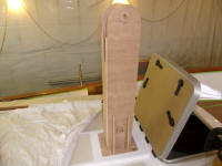
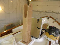
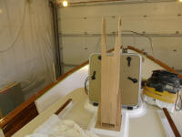
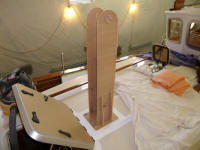
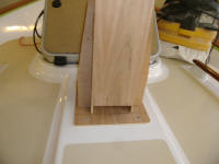
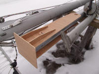
The obvious answer to the shape for the top of the
tabernacle was a clean semicircle with a 3.25" radius.
This is what a fresh approach, after stepping away from
something late in the day when the brain is tired, can
do for oneself. My earlier layouts had all trying
to be working off the 2" diameter doubler plates that I
planned around the hinge pin location, located near the
top of the tabernacle, but this arc wasn't working with
the overall shape. Only with a fresh start did I
truly realize that the top arc need not parallel the
small-diameter doubler.
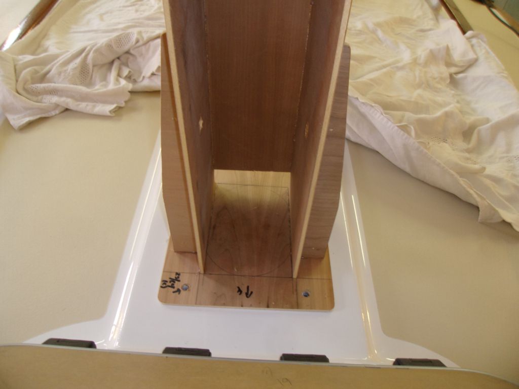
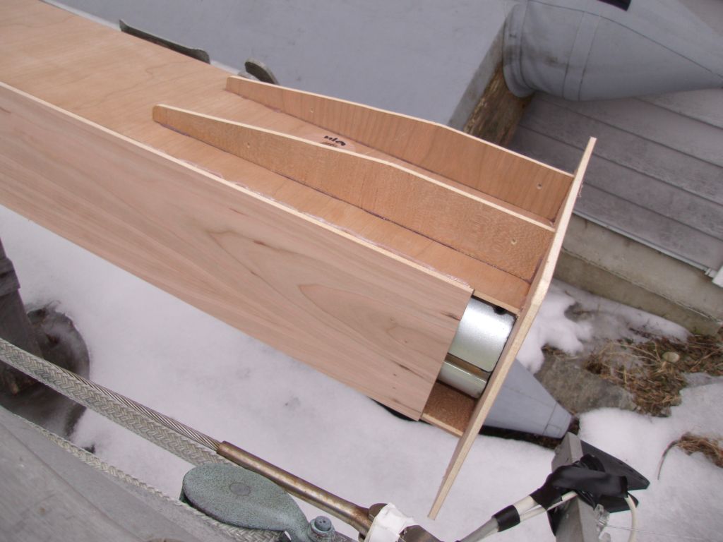
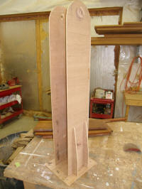
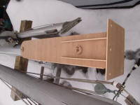
After cutting the new shapes, which I thought looked
good, I installed 2" plywood circles at the two bolt
locations; my real-world tabernacle inspiration had
welded doublers here for additional strength. The
bolts--one at the top, which would be the hinge, and
another near the bottom to pin the mast in place--would
be 5/8" diameter. |

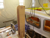 |
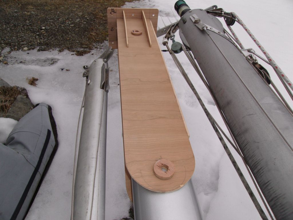
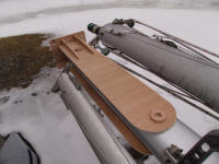
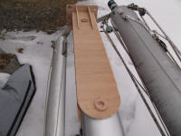
Outside, I tested the fit of the template on the base of
the mast. |

 |
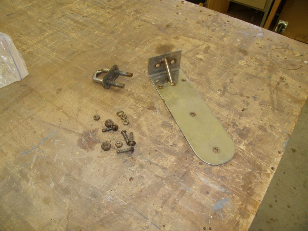
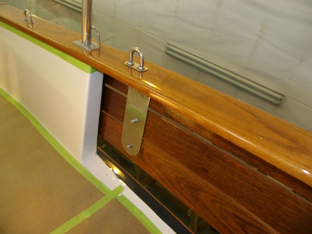
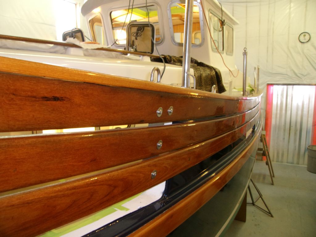
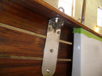
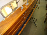
Back on board, I reinstalled the main chainplates with
new fasteners, through reusing the original U-bolts
since they were in good condition. |


 |
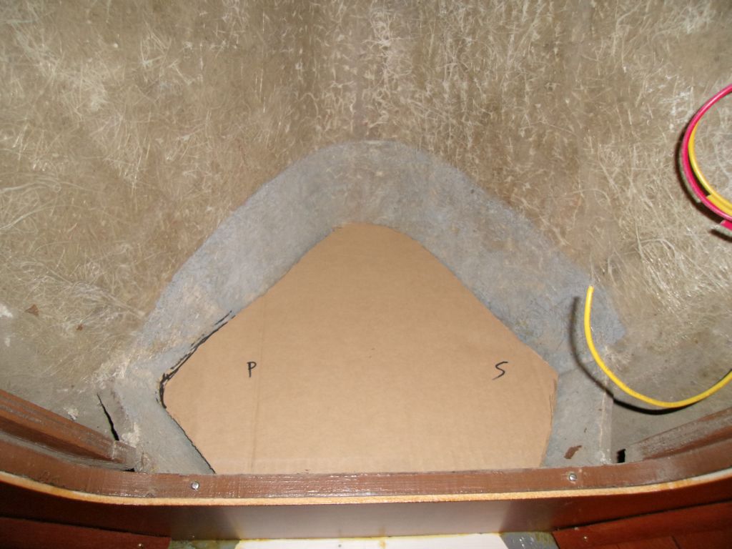
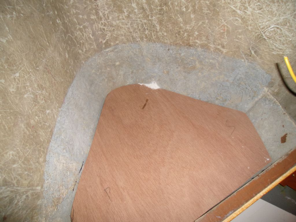
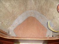
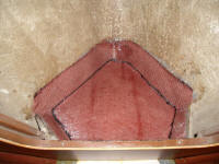
The chainlocker needed a little floor and a drain to
isolate it from the rest of the boat, and prevent water
and debris from the anchor chain from flowing into the
bilges. I made several measurements so I could
determine the basic location of the waterline from
inside the boat: the easiest way to do this for me
was, from outside, to measure down from one of the
deadlights in the forward cabin to the waterline, using
a very conservative position. Then, inside, I
could measure from the deadlight to the v-berth
platform, and, at the forward end, extrapolate the rough
position of the waterline inside the chainlocker.
This was well below where the platform needed to go, so
I proceeded with a cardboard template of the new
platform. I angled the platform down towards the
bow for drainage. Then I cut the actual piece from
12mm marine plywood. I kept the original plywood
"corners" in place within the locker, as these gave
passage for hoses and/or wiring into the chainlocker
from the space behind. |

 |
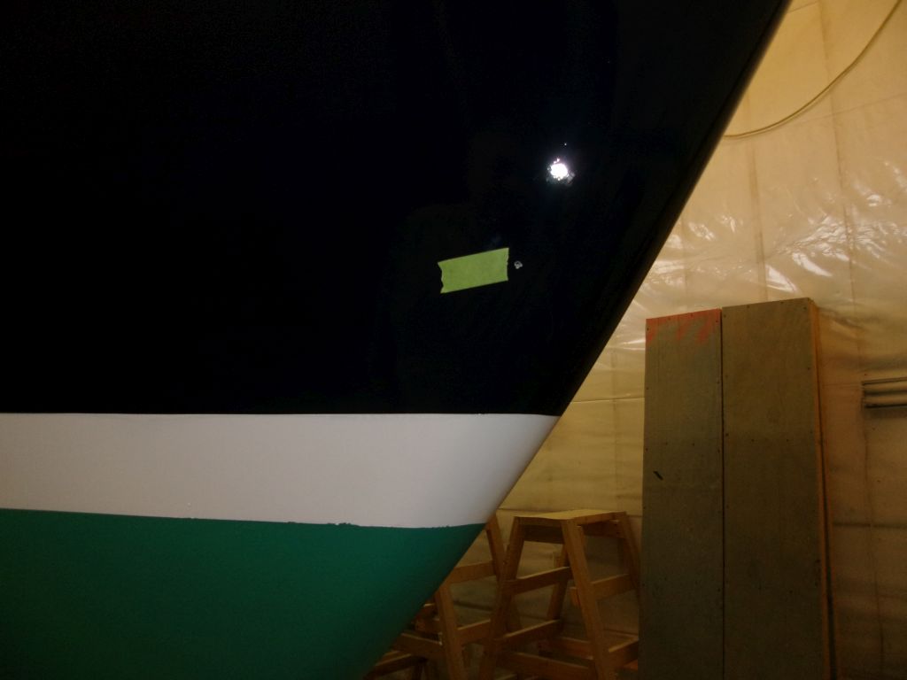
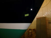
From inside, and working off the height of the finished
height of the new platform, I drilled a pilothole
through the starboard bow to determine the new drain's
location from the outside, shown near the masking tape
tab. This position was good: well above the
waterline. I'd redrill the hole with a larger bit
later, and eventually cover it with a clamshell to
channel water away from it, but I had what I needed for
now. |
 |
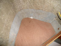
After final preparations and cleanup within the locker,
I epoxy-coated the plywood platform on all sides, and
installed it with an epoxy fillet before covering the
whole thing with fiberglass, which I extended up on all
sides to tab the platform securely in place and make it
watertight. |
 |
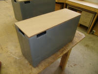
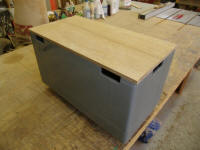
I managed to find in my scrap pile two pieces of plywood
just large enough from which to make the covers for the
two battery boxes, and trimmed them to the correct
overall sizes. I'd continue with further details
and prep another time. |
 |
| |
Total Time Today: 4.75 hours
|
<
Previous | Next > |
|
|