Project Log: Saturday, February
25, 2012
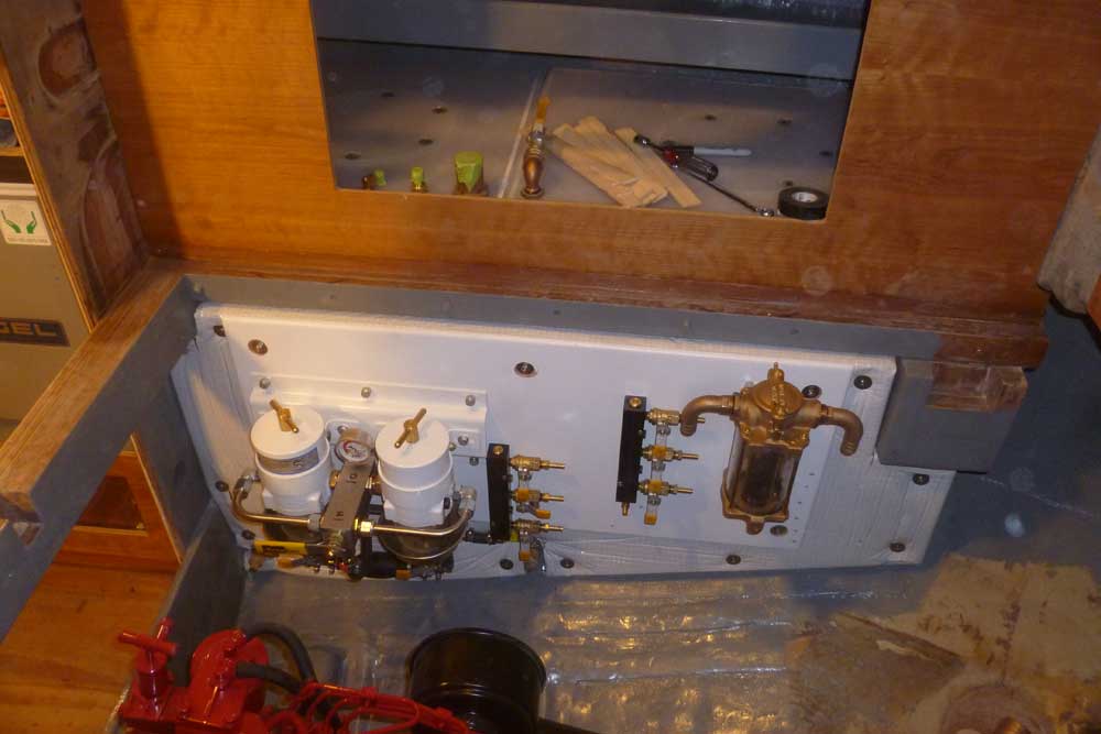
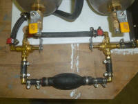
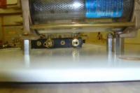
With various pieces and parts now on hand, I assembled
the section of the fuel system between the supply
manifold and the filters, incorporating a regular hand
bulb for manual filling of the fuel filters if needed.
I chose to locate the primer bulb on a separate leg,
offset by three-way valves, so that it wouldn't be a
factor in the regular fuel system in case the bulb
failed; this required more fittings, but I preferred to
keep the bulb isolated, so the tradeoff was worthwhile.
For regular operation, fuel would run through the top
section, unhindered; should manual priming be necessary,
all I'd have to do was swing the two valves to direct
the flow through the bulb and on to the filters.
Each valve handle featured a point on the end, which
pointed to the direction of flow. |
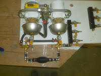 |
Regular operation
(Valve handle points up)
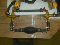 |
Primer Bulb Operation
(Valve handle points down)
 |
 |
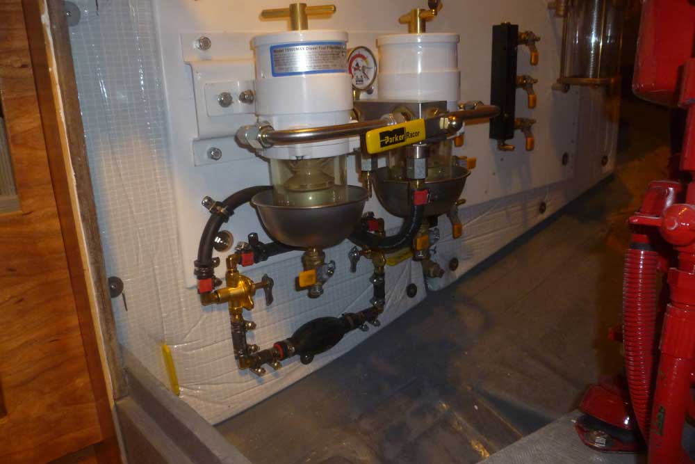
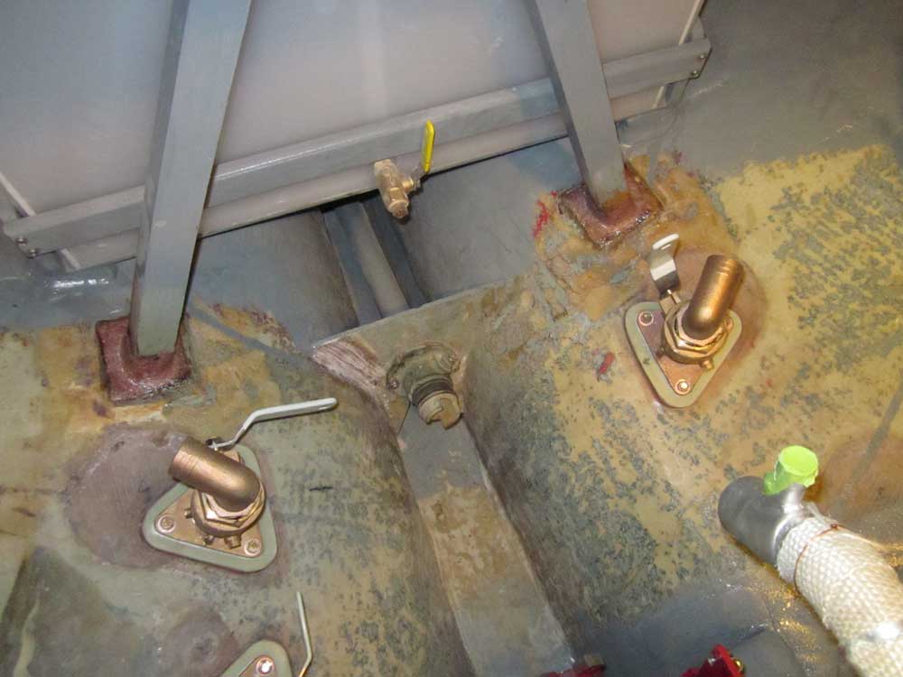
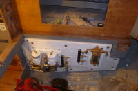
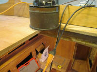
At the aft end of the panel, I installed my new bronze
raw water strainer. Because of potential
interference with the various fuel lines, which problem
I discussed earlier, I chose to mount the strainer on 1"
long standoffs, which elevated the strainer above the
fuel lines and gave me more options in placement and
operation.
Even so, the routes of the fuel lines dictated the
placement of the strainer. Before beginning, I
used a scrap of fuel hose (I'd used up most of the short
pieces earlier in building the fuel primer bulb system)
to mark out the routes of the three fuel return hoses
that would potentially interfere with the strainer's
location.
In addition to convenient use and placement of the
strainer, I had to account for operation of the fuel
system valve handles once the hoses leading to the
strainer were in place, so in the end a location at the
upper aft corner of the panel worked out best.
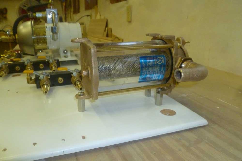
After marking the location, ensuring that the fuel hose
runs were clear of the strainer mounts, I secured the
standoffs to the panel from behind with machine screws,
and installed the strainer to the other side of the
female standoffs with additional screws. The
height may appear as if it would be wobbly or tenuous,
but the standoffs were very strong and there was no
tendency to sag, wobble, or compress the plywood. |

 |
In fact, once the plywood panel was reinstalled in the
engine room, I found that even applying weight to the
strainer only caused the panel itself to flex slightly
between its mounting bolts, but there was no movement
beneath the standoffs. I'd been prepared to add
fender washers between the standoffs and panel if
needed, but this did not seem necessary.
|
 |
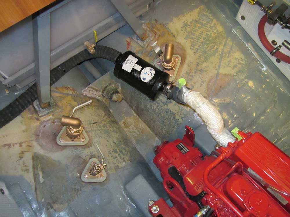
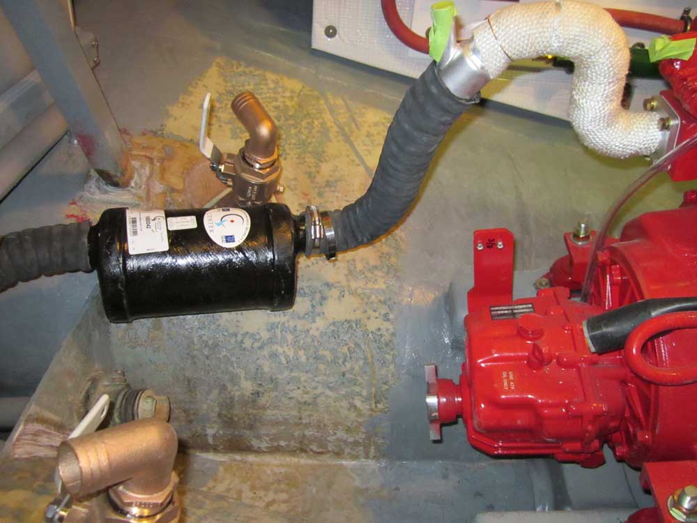
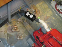
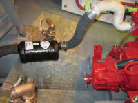
Although I was not yet ready to permanently install an
engine exhaust system, I needed proof of concept so I'd
know how and where I'd eventually lead the hose.
To that end, I purchased a cylindrical, inline waterlift
muffler (Vernalift), which during earlier planning had
seemed an attractive option for the tight space,
particularly since it allowed me the most height between
the engine exhaust elbow and the waterlift inlet port.
Ideally, I wanted 12" or more vertical space, and this
unit allowed that where no other shape would.
With a couple short pieces of 2" corrugated exhaust
hose, I mocked up the muffler to see where it might
naturally end up. For some reason I'd originally
been planning to run the exhaust hose down the port side
of the boat, but soon it became clear that the starboard
side offered a more advantageous hose run. I'd
have to come up with a way to secure the muffler in
place, which wouldn't be too difficult, and the mockup
showed a need for various chafe gear to protect the hose
in the proposed locations, but overall it looked pretty
good, so I knew I could proceed with other engine room
work knowing the exhaust system had a home. Final
installation would come some time in the future,
whenever it made sense. |
 |
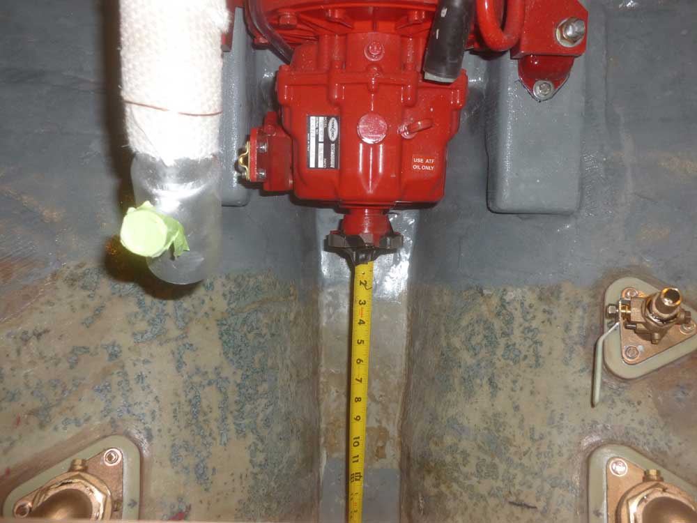
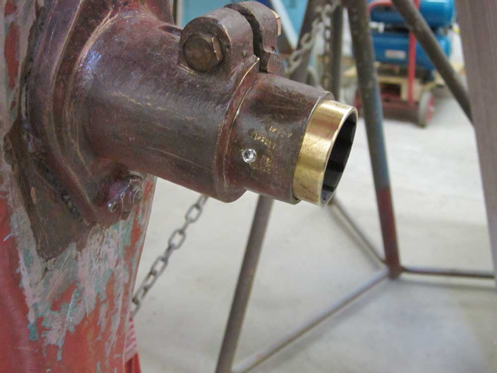
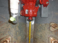
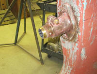
One installation I wanted to complete before
contemplating the exhaust was the propeller shaft, so I
ran a tape measure up through the stern tube and secured
it with tape to the center of the transmission hub, then
noted the measurement at the outboard end of the shaft
log: 53-1/8". |
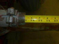 |
To this measurement, I'd need to add length as needed to
incorporate the propeller and shaft taper, plus
clearance distance between the bearing and prop hub.
Also, I added 3/8" immediately to allow for the
protrusion of a new Cutless bearing, which I installed
next as an afterthought, beyond the end of the tube.
Shaft diameter would be 1-1/4". |

 |
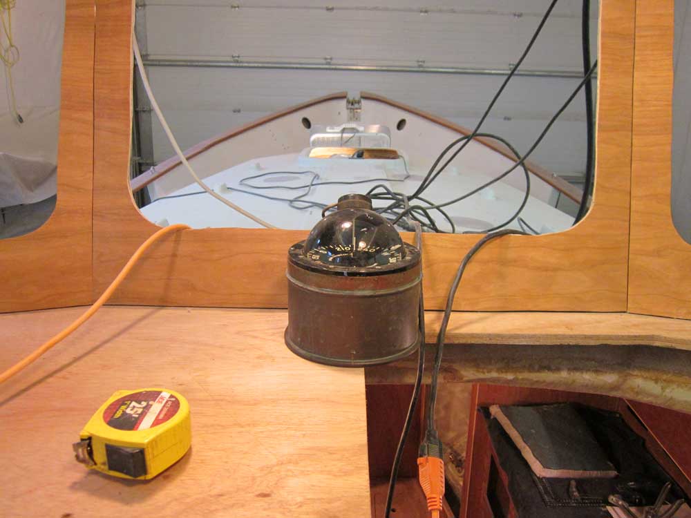
Earlier, a reader asked where I planned to put my
compass, something I'd had in mind but had never
included in any of my helm and pilothouse mockups.
I'd been saving a nice bronze binnacle and 6" compass
that I'd had for years, and planned/hoped to install it
on the centerline in the pilothouse, directly aft and
beneath the center window.
Although not directly in front of the helm per se, this
location was easy to see, and with only half a step
sideways the helmsman could be directly behind the card
as needed; also, the location did not interfere with any
other installations, and would be far enough removed to
avoid undue electrical interference in the helm area, at
least to the point that it could be properly compensated
for. However, the binnacle did hang slightly over
the companionway; I thought I could deal with that
appropriately during the finish and trim stages of
construction. In any event, this was my current
thinking, lest anyone think I'd not considered this
still-critical piece of navigation equipment. |
 |
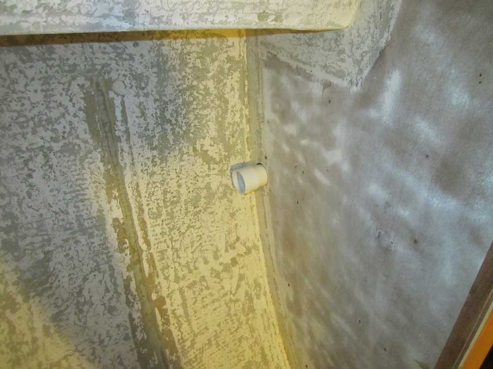
One odd and end that I thought I should take care of was
the short continuation of some 2" PVC conduit I'd run in
the galley earlier. I'd located this conduit
behind the stove to allow for wire and hose runs as
needed, and wanted to extend it forward to the hanging
locker. This was simple and straightforward, and
probably the only reason I'd not done it sooner was that
I'd not had PVC cement on hand. I added a tee
beneath the galley sink cabinet in case I needed/wanted
to lead a hose or wire into that space, but mainly I
expected the conduit to be used to lead between the
forward and after parts of the boat through the galley.
At the forward end, I installed a coupling to allow for
future extension. |
 |
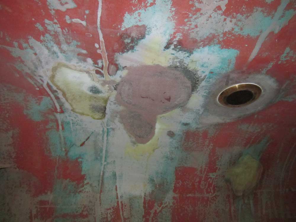
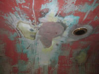
Also in the "miscellany" department, I sanded the first
layer of fill on the old depthsounder patch, revealing
just a couple small low spots to fill and smooth.
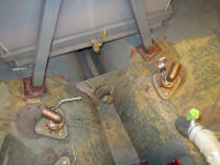
Meanwhile, I installed some tabbing around the bases of
the mizzen mast A-frame support, which would help hold
the legs in place as needed. |
 |
| |
Total Time Today: 8.25 hours
|
<
Previous | Next > |
|
|