Project Log: Wednesday, July 4, 2012
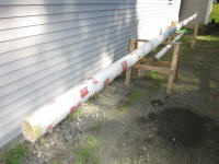
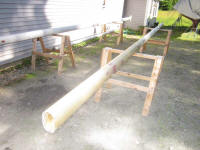
Earlier in the week, I sanded the epoxy-filled holes in
the masts and, after a day's rain delay, applied a
second coat of filler as needed. I overfilled the
holes so I'd not have to reapply a third time, as I
hoped to use a weather window late in the week to prep,
prime, and paint the spars. |
 |
I received a shipping crate containing my new center
pilothouse window and sliding door, which I'd ordered
from AJR Windows. |
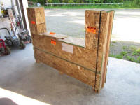 |
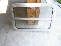
This is the new window. I test-fitted it in the
opening to check the size, but didn't manage any photos
of it in place at the time. |
 |
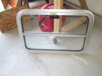
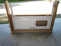
This is the new sliding door, made of aluminum with a
powder coat finish. There was a little abrasion
damage to the finish where the cardboard surrounding the
pilothouse window, which had been wedged inside the same
crate, had rubbed during transit, but I'd not addressed
or resolved this issue as of this writing.
|
 |
I spent most of the day on plumbing, both the potable
water system and heating system. To begin, I made
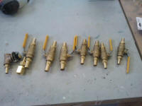
up a series of shutoff valve assemblies that would
isolate certain components--specifically the water
heater--from the system for potentially easier
maintenance. There were shutoff valves for the
potable water cold and hot tank connections, the heating
system in and out, and two others that I'd install in
the heat exchanger lines running from the engine. |
 |
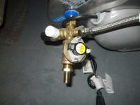
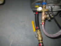
To begin, I installed fittings on the water heater for
each of the four connections required: potable
water in and out, and heat system in and out.
Earlier, I'd determined that three of these connections
required 1/2" NPT female adapters, while for some vexing
and unidentifiable reason the hot water discharge
required 1/2" BSP threads. The illogic of
component manufacturers will forever make me shake my
head in wonder.
In any event, the way I wanted to plumb the tank
required that I use an expensive BSP to NPT adapter for
this one fitting, which I'd sourced and ordered earlier.
This is the fitting seen on the far right, just above
the hose barb. |
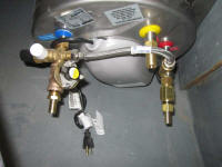 |
On the cold water supply, located to the left in the
photo above, I installed an aquastat sensor, which
required that I use a bronze tee fitting. This
sensor would monitor water temperature, and trigger the
boiler to turn on when it noted cold water entering the
tank. My advisor at the heating system supplier
suggested that this tee and sensor should be well
insulated, which I'd do later. |
 |
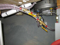
Next, I completed the potable water runs to and from the
tank, installing shutoff valves in line. |
 |
Over the past months, I'd slowly adapted my own
heating/water system diagram from the basic guidance in
the instruction manual, to reflect exactly the situation
I had on board. With so many components and no
past experience to guide me, I'd chosen to let things
mostly work themselves out along the way, and indeed
they had done just that, though not without plenty of
careful consideration and planning along the way.
At some point I'll create something readable for public
consumption, but from my rough sketch I determined the
heating system runs to and from the tank. These
lines would provide the heat transfer required, and the
system coolant could be heated either by the engine heat
(through a slim heat exchanger specifically designed for
this purpose), or from the diesel boiler itself.
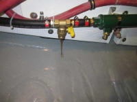
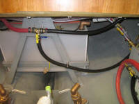
At the outlet of the separate engine heat exchanger, I
installed a drain/fill valve for the heating system, as
this represented the low point of the system. This
valve included a garden hose hookup for convenience.
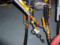
From here, I led a hose to one side of the water heater,
with a shutoff valve just before the connection.
From the other side of the water heater, I led a similar
hose to one side of the summer 3-way valve, which I'd
mounted earlier. |
 |
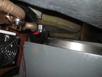
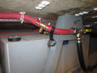
From the final side of the summer valve, I ran a hose up
and around to the inlet side of the pilothouse fan
heater, beginning the actual heat runs. From here,
another hose would eventually lead to the main cabin fan
heater, before returning to a new tee fitting that I
installed on the other side of the summer valve. |
 |
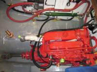
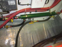
To provide engine-heating capacity for the system, I
needed to connect the engine's cooling system to the
boiler's heat exchanger. So from the outlet side
of the engine, from a fitting installed specifically for
this purpose, I ran a hose (with shutoff valve) to one
side of the heat exchanger. Then, I prepared a
stub with shutoff valve from the other side of the heat
exchanger. |
 |
This was the end of the day's work, but later I'd
continue that outlet hose up to the remote engine
expansion tank (the red tank located on the port side of
the pilothouse behind the cabinet), and then finally
back to the other side of the engine's own heat
exchanger, completing the loop. Complicated and
convoluted? You bet. More so than I wanted,
but such are the realities of systems installations in
small boats. |
| |
Total Time Today: 7 hours
|
<
Previous |
Next > |
|
|
