Project Log: Friday, April 25, 2014
I'd ordered a little push button switch that I planned
to use for the refrigerator compartment fan, which I'd
be installing on the same wiring circuit as the refer
but wanted switched independently. Unfortunately,
I discovered too late that the switch was momentary
only, and unsuitable for the intended task, which would
have been a setback since I really wanted to finish up
the work in this compartment and move on.
Fortunately, I found a rocker switch in my inventory
that I could use. Normally I hate rocker switches
because the rectangular holes are unnecessarily
irritating to cut in tight places, and the fit of the
switch itself is always fussy, and the switches are to
bulky, but here it was a matter of getting the job done.
The switch would be within the cabinet anyway and not
visible.
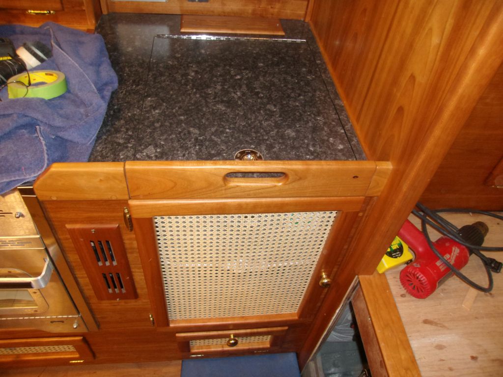
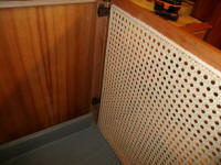
I installed the switch in the upper corner of the
refrigerator cabinet where it'd be easily accessible,
but out of sight.
|
 |
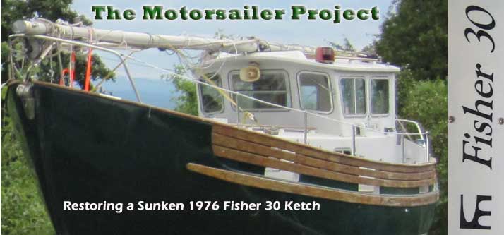
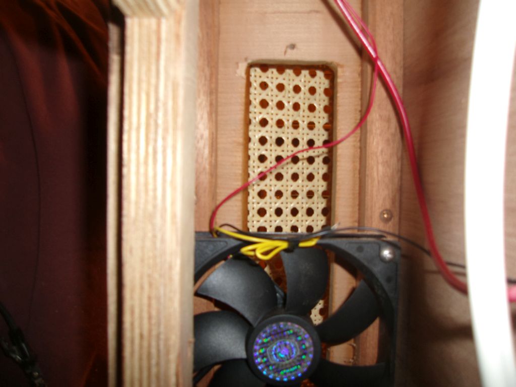
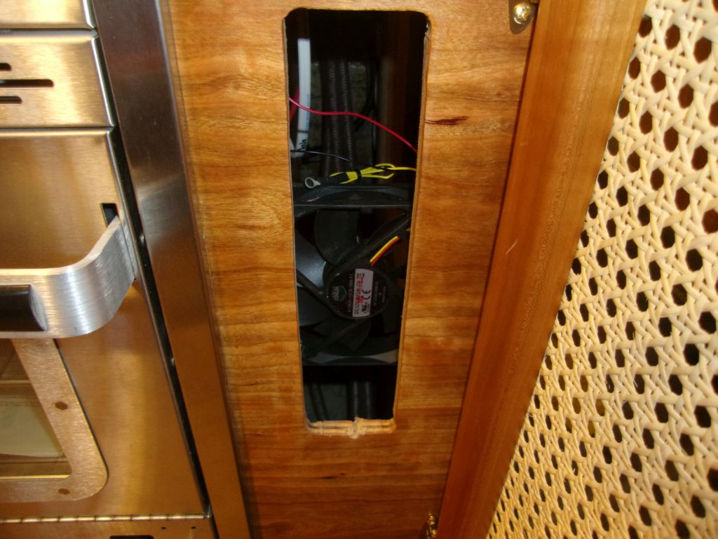
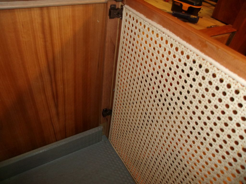
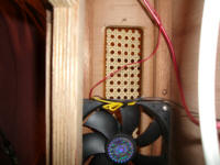
Inside the narrow utility space next to the locker, I
installed a 4" computer fan to draw additional air
through the space and hopefully promote ventilation, and
wired it as needed to the switch and the nearby terminal
block for the refrigerator circuit. |

 |
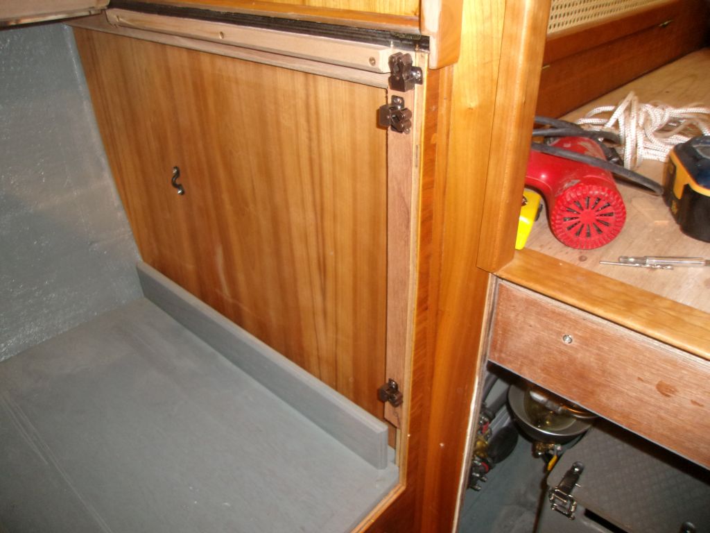
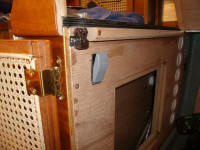
I'd not yet installed catches on the door to the refer
locker for whatever reason, so I took care of that next.
This was one of those projects that took 500% longer
than it should have, thanks to an endless need to go up
and down the latter to retrieve this tool or that
fastener or some such.
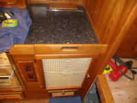
To provide a landing zone for the door catches, I needed
a filler strip within the cabinet to bring the surface
flush with the face frame, and the first piece I cut
here didn't work, since I'd not paid attention to the
depth of the latch body itself, so my first strip was
too narrow, and I had to cut a wider one. More
trips. But at long last, the task was done. |
 |
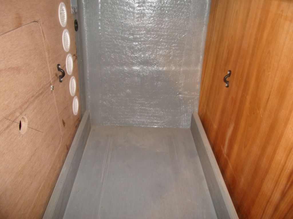
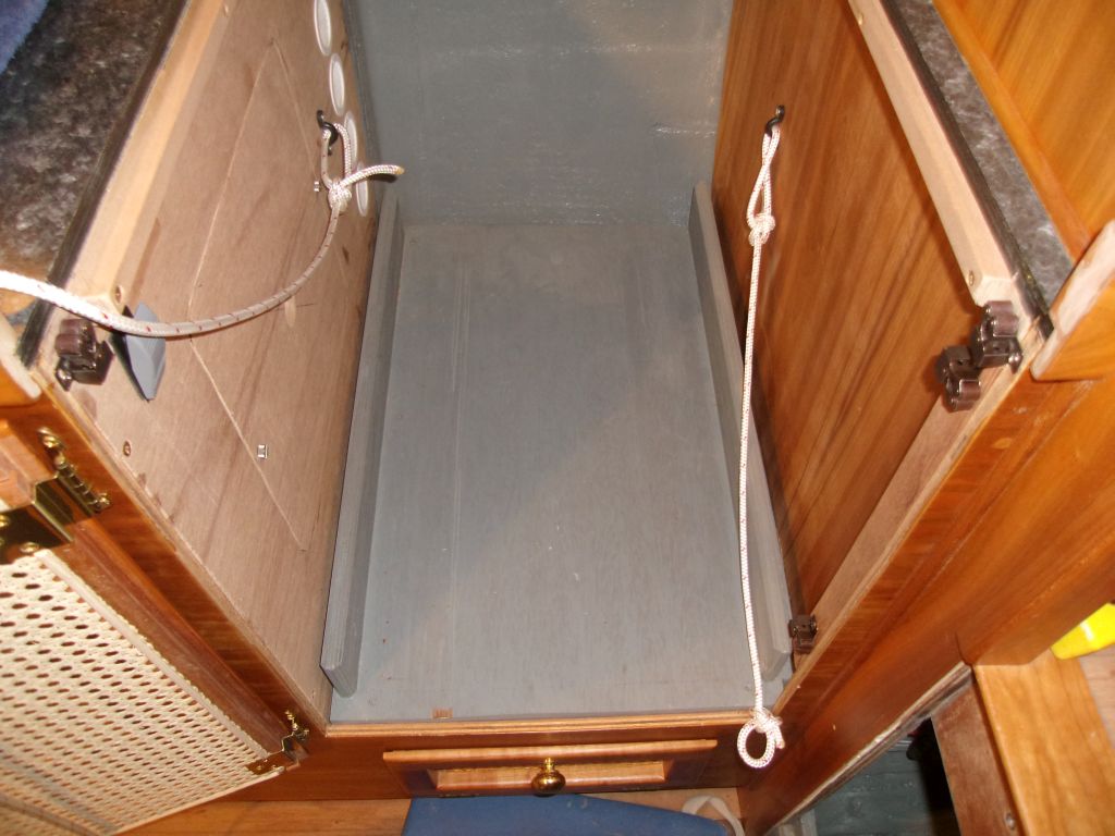
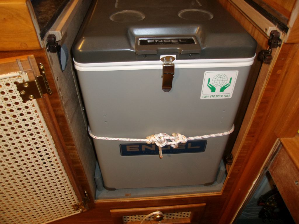
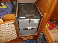
To secure the refrigerator in the cabinet, I wouldn't
rely on the door, but needed some other means. It
was well restrained fore and aft, and against the hull,
but could slide out through the opening. There
were probably any number of ways I could have done this,
but in the end I chose a simple lashing, run between a
pair of eye straps that I secured to the two bulkheads
deep in the cabinet. |


 |
By now, midway through the day, the weather had warmed
up, and with inclement weather forecast for over the
weekend I knew I should get to work outside on the
spars, where plenty of critical work remained.
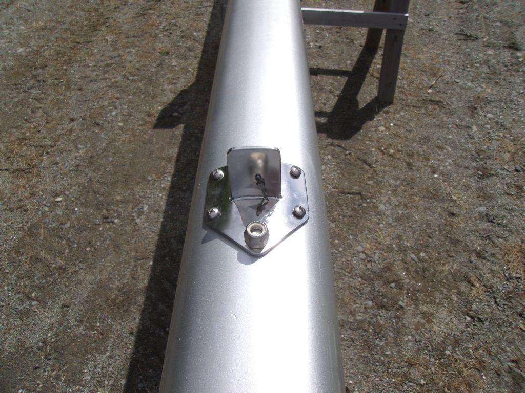
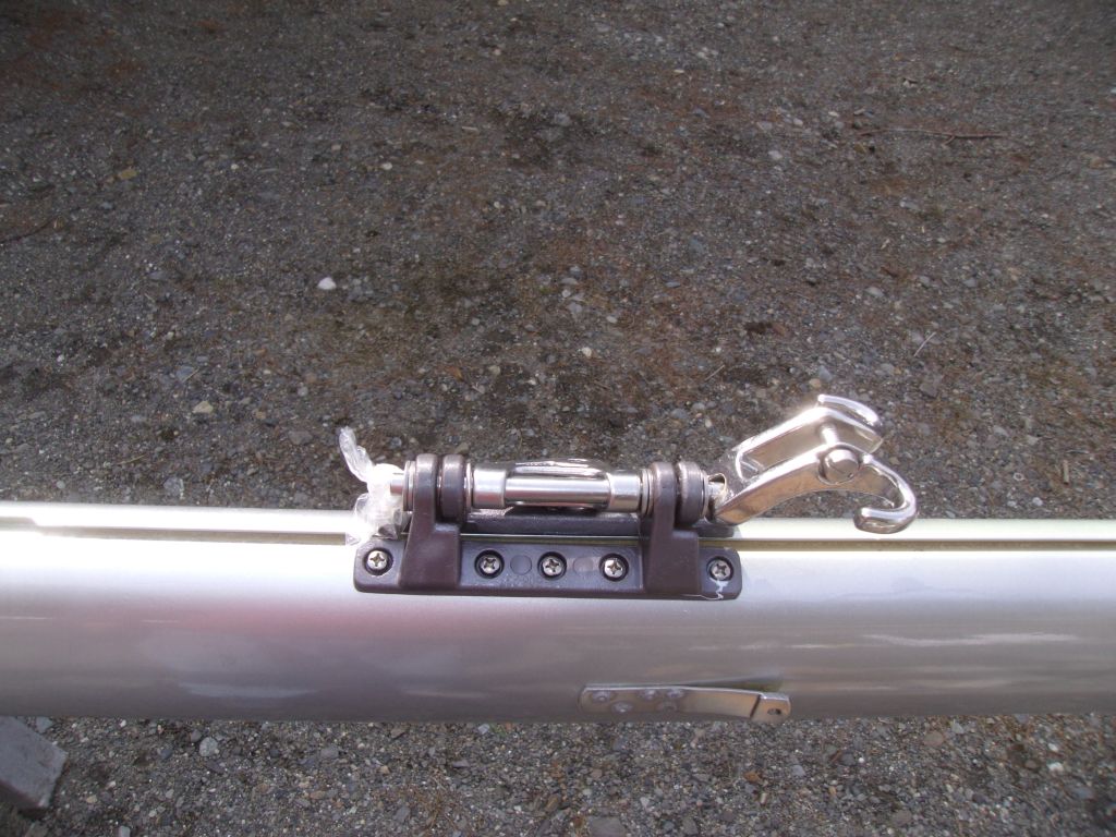
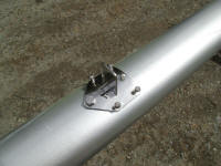
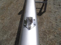
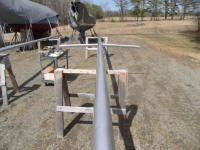
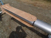
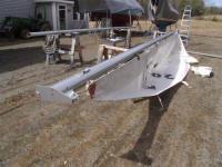
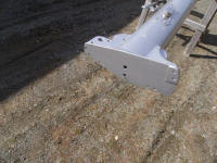
I started with the new spreader bases, which I'd had
fabricated earlier in the project, along with new
airfoil spreaders. The original
tubular spreaders and bases had been sort of flimsy, and
were
just plain ugly and droopy. I hate
droopy spreaders.
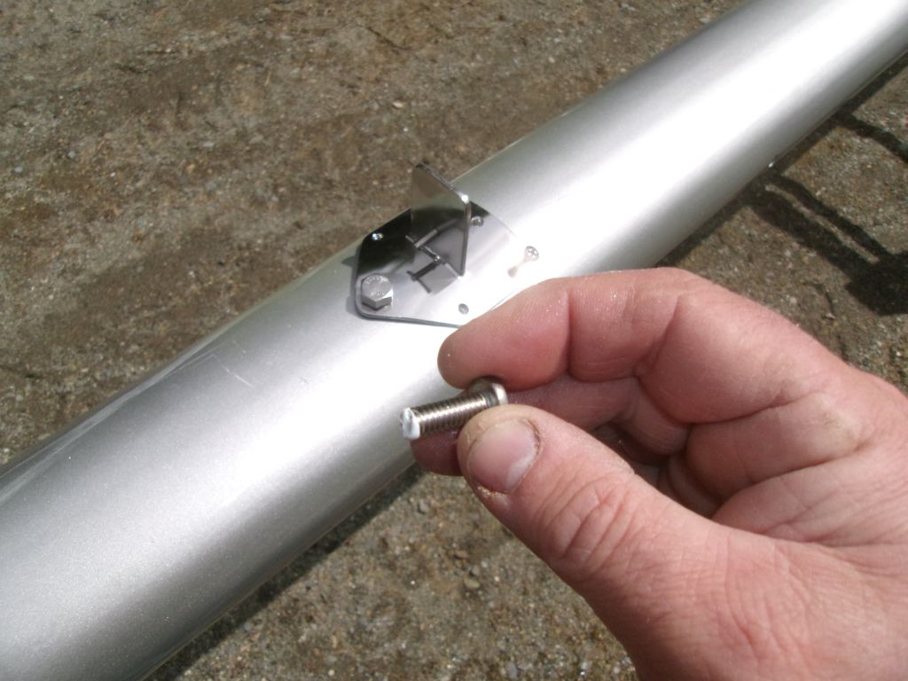
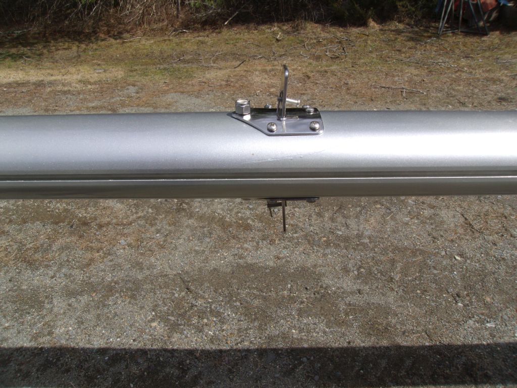
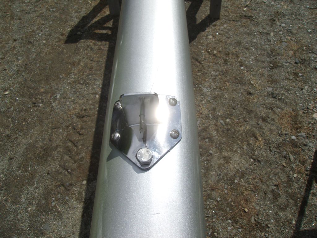
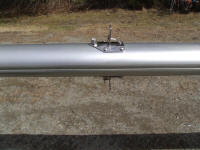
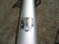
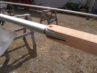
Installation was cheerfully straightforward. I
secured the two bases with a bolt through the spar
(incorporating a spacer cylinder within the spar), which
held them in position while I drilled and tapped for
five machine screws in each base. Then, I removed
the bolt, cleaned out drill spoils, and reinstalled the
bases with a light coat of Tef-Gel on the bonding
surface of the base, plus on all the screw threads. |
 |
I'd erred in determining the length of the through bolt
required. The original bolt had been galled, and
during removal I'd twisted the end off with the nut.
My new bolt was not long enough to allow the lower
shroud tangs to be installed, and in fact didn't even
have enough exposed threads for the nut that I used, so
I ordered a longer one, and would complete that
installation once it arrived.
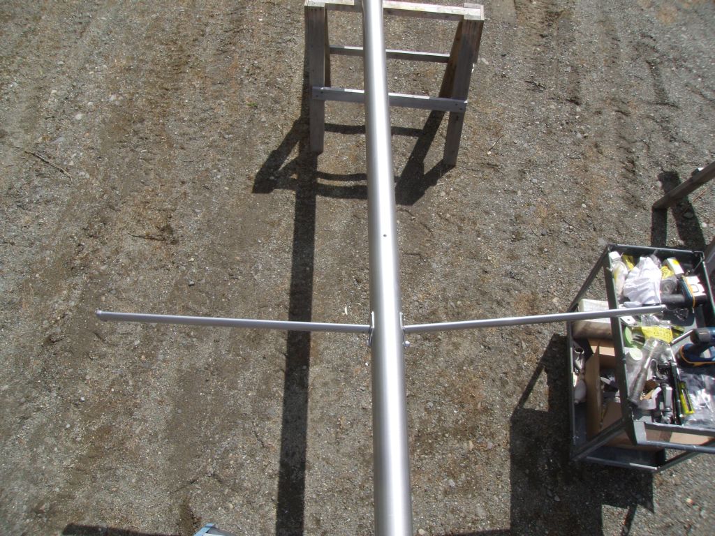
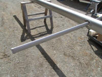
For now, I mocked up the new spreaders to check them
out, then removed them for storage for the moment. |
 |
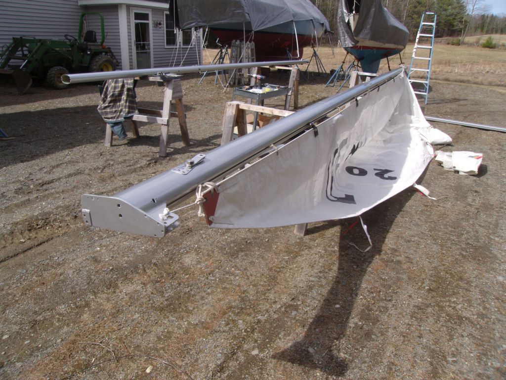
I was thinking that before I got too far into the mast
reassembly, I'd get the wire runs out of the way.
But as I was starting to look into that project, I
noticed that the wind, which had been brisk all morning,
had died, and with the relative calm I thought it would
be a perfect opportunity to figure out where the new
booms and goosenecks needed to go: for this, I'd
need to rig the sail temporarily, something I'd not wish
to do on a windy day.
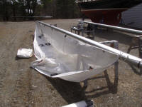
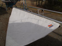
I "hoisted" the sail in its groove, and discovered an
issue that I'd need to deal with: the regular slot
intended for slide installation was too short for the
long slides at the forward ends of the full batten
pockets (Harken Battcars). There was another slot
further down, where the original sliding gooseneck car
would have been installed onto the track, and that
worked to get these cars in the slot for now, but once I
installed the fixed gooseneck, this would no longer be
possible. I'd need to enlarge the upper slot to
allow these cars to fit. |
 |
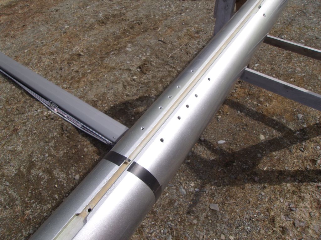
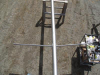
Before continuing, I slid the tabernacle mockup into
position and marked its top edge on the spar for
reference, to ensure that my gooseneck remained above
this point. |
 |
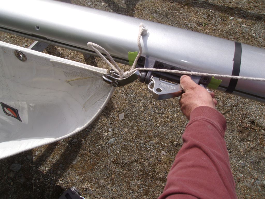
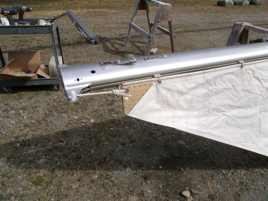
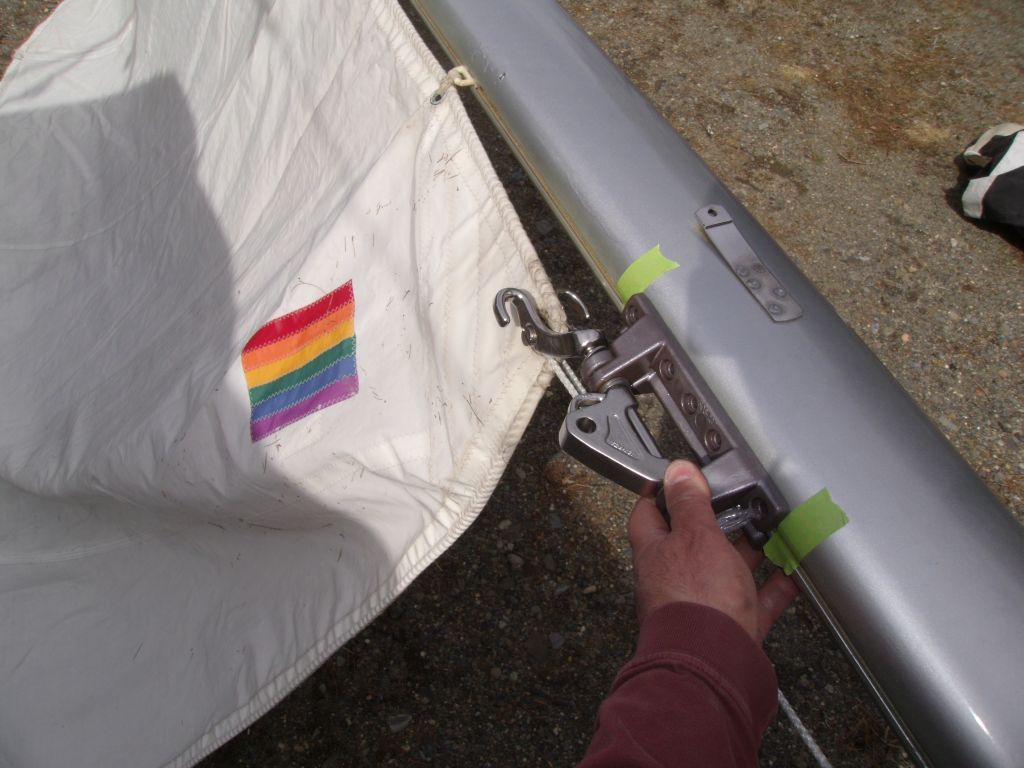
I secured the head of the sail near the masthead,
leaving ample room for the headboard shackle, splice,
and/or knot, then stretched the sail at the tack with
another line. Then, I secured the tack to the
gooseneck pin, and let the gooseneck assembly fall where
it may from there, making reference marks with tape on
the mast. |
 |
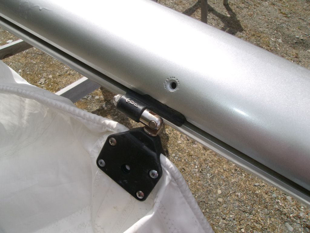
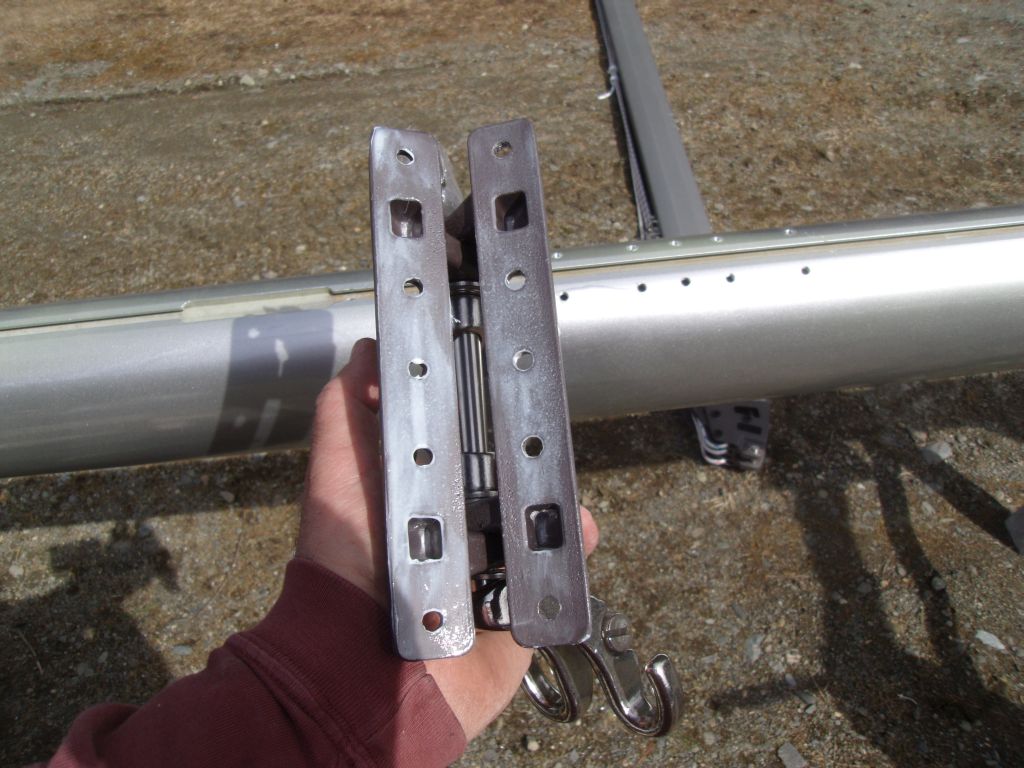
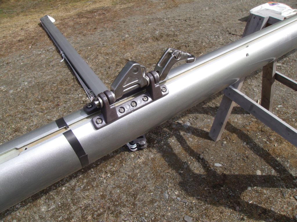
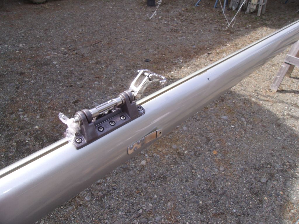
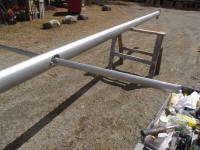
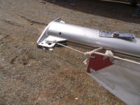
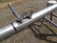
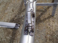
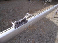
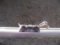
After putting away the sail, I prepared the gooseneck
for installation. The fitting itself was a
"universal" gooseneck, with a hinged design that allowed
it to fit many spar sections. I laid it out as
needed and drilled and tapped for machine screws, before
coating the back of the gooseneck in Tef-Gel and
installing it permanently with ten of my favorite screw
type, 1/4" cheese head (fillister) machine screws. |


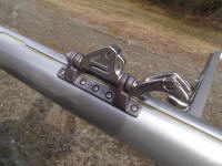 |
I repeated the process with the mizzen mast, which used
the same gooseneck fitting. |


 |
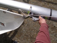
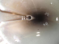
By now it was growing late, but I wanted to at least get
my snake run through the mast for the wiring. My
earlier, albeit brief, foray into this task had shown
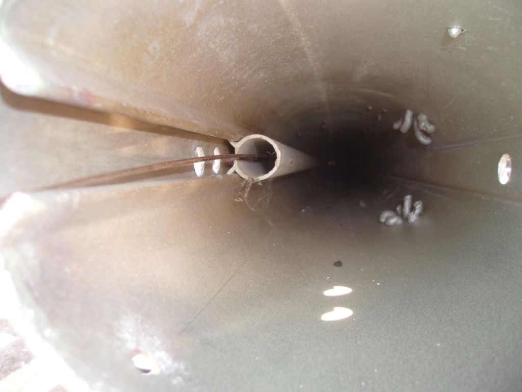
that it would be a challenge. The mast
incorporated a plastic wire conduit into the inside of
the extruded groove on the aft side of the mast, a nice
system because it would protect the wires and prohibit
wire slapping.
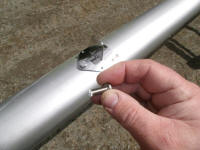
The problem was that the conduit ended short of the top
of the mast, and with the interior welded sheave support
structures at the top, plus a welded top cap, there was
no direct access to the wire conduit: just a pair
of holes in the top cap. I found I could peer into
one hole and feed the snake through the other, but I
wasn't able to get the snake into the conduit from the
top.
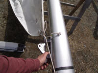
From the bottom, it was easy to get the snake started,
and up to the masthead, but then I had to find a a way
to get it to come out the small hole at the cap--not an
easy or natural thing. So with some effort, and
two flexible grabby tools, I managed to first direct the
end of the snake towards the proper hole (with one
flexible tool inserted from the side through a small
hole intended for a sheave pin), then, with the end of
the snake near the hole, use the second grabby tool to
grab it from the top of the mast cap, and
eventually--and with great ceremony--pull the snake
through the top. |
 |
I left things as is for now, not wanting to attempt to
fuss with wires this late in the day. I had a
feeling that getting the wires down and into the chase
successfully from this small top hole was going to be
its own challenge, best left for another time. I
needed one wire pair and a VHF cable at the masthead,
and another wire pair to the midpoint of the mast (where
a hole already opened up into the conduit). |
| |
Total Time Today: 6 hours
|
<
Previous | Next > |
|
|