Project Log: Friday, March 21, 2014
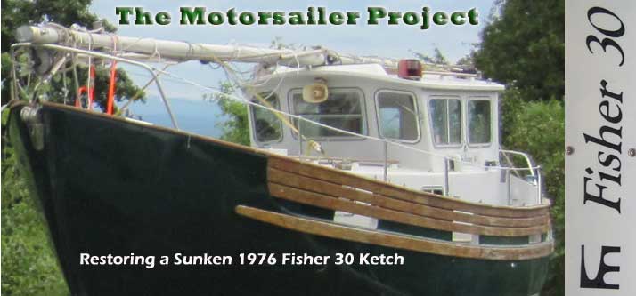
Though not my dream finish, I decided to simply paint
the raw fiberglass overhead in the head. While the
surface was naturally somewhat rough, as unfinished
fiberglass tends to be, it was essentially flat and
consistent, and with several coats of paint would end up
looking OK. I didn't know what else to do in this
tiny space, and wasn't about to go down any complicated
roads at this stage of the game. Some other time,
perhaps, but I had a feeling the paint would end up being
completely adequate for what was needed in this space.
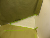
To prepare, I masked off as needed. I'd already
sanded the fiberglass long ago during the initial stages
of the refit, so other than cleaning it was as ready as
it was going to be. The nature of the exposed
glass here (and in other areas of the overhead/cabin
trunk, though those were all now covered) was a sort of
furry texture, as sanding tended to always pull out
dry-ish strands of chopped mat (which were part of the
laminate structure). More sanding only exacerbated
this, so I decided to more or less petrify the surface
with the first coat of primer, rather than concern
myself with otherwise stabilizing the material. I
figured that when the primer dried, I'd be able to sand
more smoothly for the final primer and paint coats.
Preparations complete, I applied a coat of primer to the
overhead, cabin trunk, and the small area of exposed
hull near the toilet platform.
|

 |
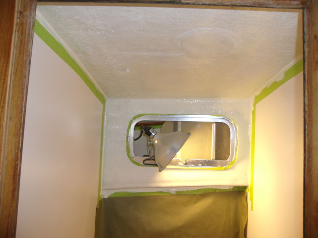
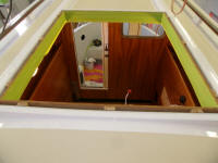
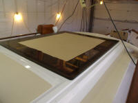
To complete the overhead in the pilothouse, I ordered a
tinted 1/2" thick acrylic panel for the large hatch
opening. I'd long ago decided to forego the
opening nature of this hatch (as per original), as I saw
no need for the opening myself, and numerous pitfalls to
the idea. The fixed panel would provide light and
upwards vision. I had the panel cut to size and
edge-polished, with radiused corners. I selected
dark bronze tint for the panel since I preferred that
shade to dark gray, and felt the panel needed to be
quite dark to limit UV problems and basic annoyance in
the space below.
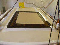
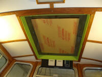
I test-fit the panel to ensure that the measurements
were as I'd specified. I'd begun by masking off
the trim inside the opening, as at first I had
anticipated installing the panel shortly, but realized
that I'd not yet received the critical primer required
for the bonding system, so I had to change my plans
pending its arrival. But the panel fit well and
looked good. I have to do something with the old
holes left from the original sliding tracks, filling of
which apparently slipped my attention during final
painting preparations, by which time I'd already decided
to eliminate the slides. |
 |
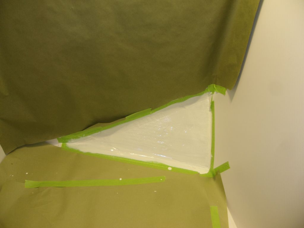
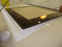
The large size of this panel, and the natural potential
expansion and contraction of the material, required a
flexible bonding system, with no fasteners, so I
selected a polyurethane adhesive sealant designed for
bonding polycarbonate and acrylic windows (Sikaflex
295UV). The natural movement of the plastic would
tend to cause cracks or leaks at any fastener locations,
leading to the requirement for a fastener-free
installation system.
To ensure a high-strength bond, the manufacturer
specified a proprietary primer product (apparently made
from ground-up unicorns, which would perhaps justify its
cost). While I had ordered this, I'd not yet
received it, as I discovered. So I'd
continue this installation project another time.
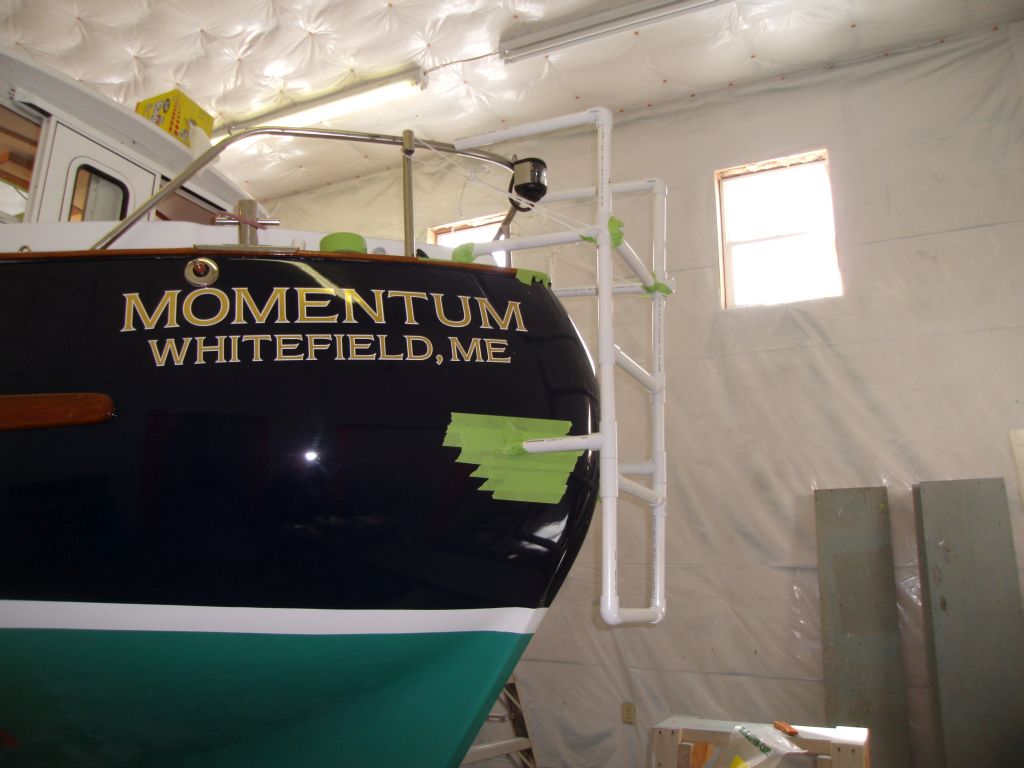
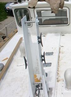
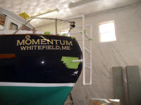
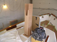
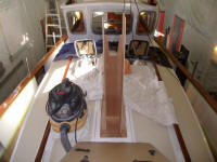
Meanwhile, continuing to try out ideas and basic
positioning--a test bed, not to represent an exact final
appearance given the severe limitations of my chosen
template medium--I made a few changes to my plastic
ladder mockup. If you can't see past the raw
nature of this, with all its flaws and obvious
mockup-ness, then please avert your eyes. It'll be
over soon.
Seen here is another idea where the vertical rails could
potentially curve into a horizontal member and mate with
the stern pulpit. |
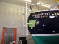 |
Really what I hoped to achieve at the top end, both for
support of the ladder itself and for ease of use, was an
arched rail that continued from the vertical ladder
stiles and, in a smooth curve, conjoined with the
rail-mounted bases at the top, but of course I couldn't
exactly do that in plastic. But soon I'd
need to find and meet with a fabricator who could help
me with the strength and design limitations of stainless
steel tubing, the actual material for the job.
Another templating project that I'd had awaiting my
attention was for a mast tabernacle. I'd always
dreamed of being self-sufficient in terms of mast
stepping and unstepping, by far my least favorite aspect
to annual boat commissioning. With hydraulic
self-launching trailers, I could launch the boat
(theoretically) anywhere, but the requirement to get
masts stepped has always required a crane, usually at a
boatyard. This is always an unfulfilling (and
around here, expensive) process. While the
practical aspects of self-masting in this way were
something I'd not yet tried on my own, the stubby spar
and overall setup on this boat seemed to cry out for a
tabernacle.
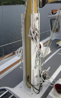
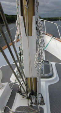
Some time ago, I communicated with another Fisher 30
owner who had a tabernacle set up on his boat, and he
was kind enough to send me numerous pictures and
measurements of the tabernacle. (He was also
instrumental in sending me key boom measurements that I
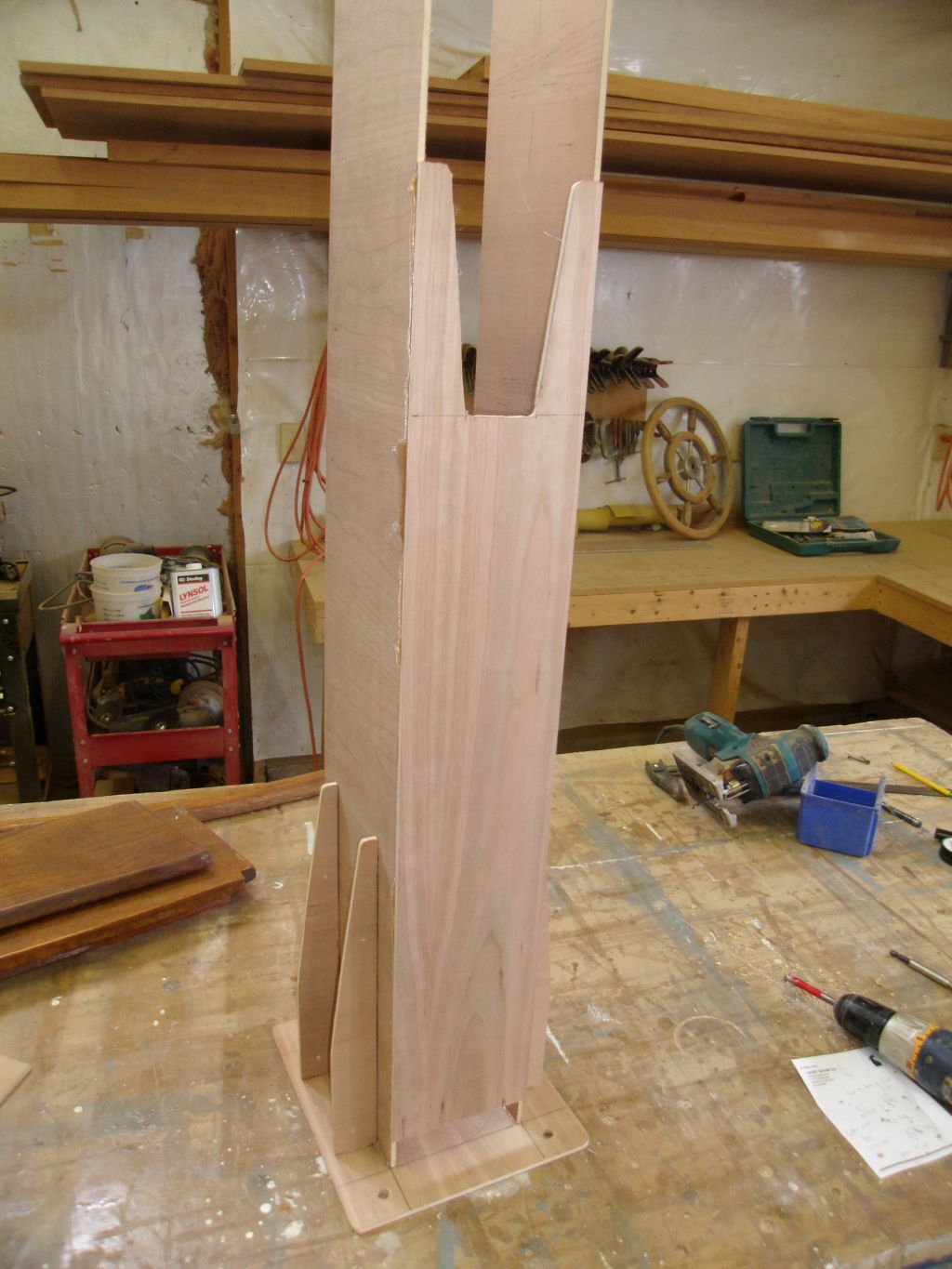
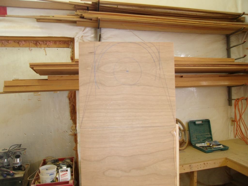
needed to replace my missing booms.) From these
helpful photos and key measurements, I spent the
afternoon building a plywood template of a proposed
tabernacle, more or less identical to the original
inspiration, but with a few small changes designed to
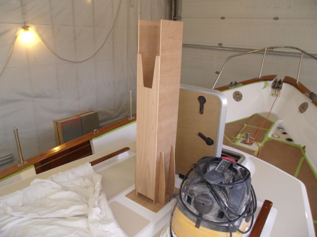
suit the needs of my boat. For example, I
extended the aft plate down closer to the deck (still
leaving an opening for drainage) since I hoped to
install my rigid boom vang bracket there, on the
tabernacle, and couldn't determine any other reason why
the original plate ended where it did. |
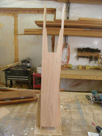
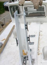 |
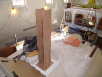
I built the template from leftover 1/4" plywood,
simulating the actual thickness of the aluminum or SS
tabernacle, and built it as accurately as I could
according to the overall measurements of the actual
tabernacle I was copying, since once I got the version I
liked I wanted the template to be something the
fabricator could directly refer to for measurements. |

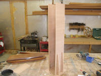 |
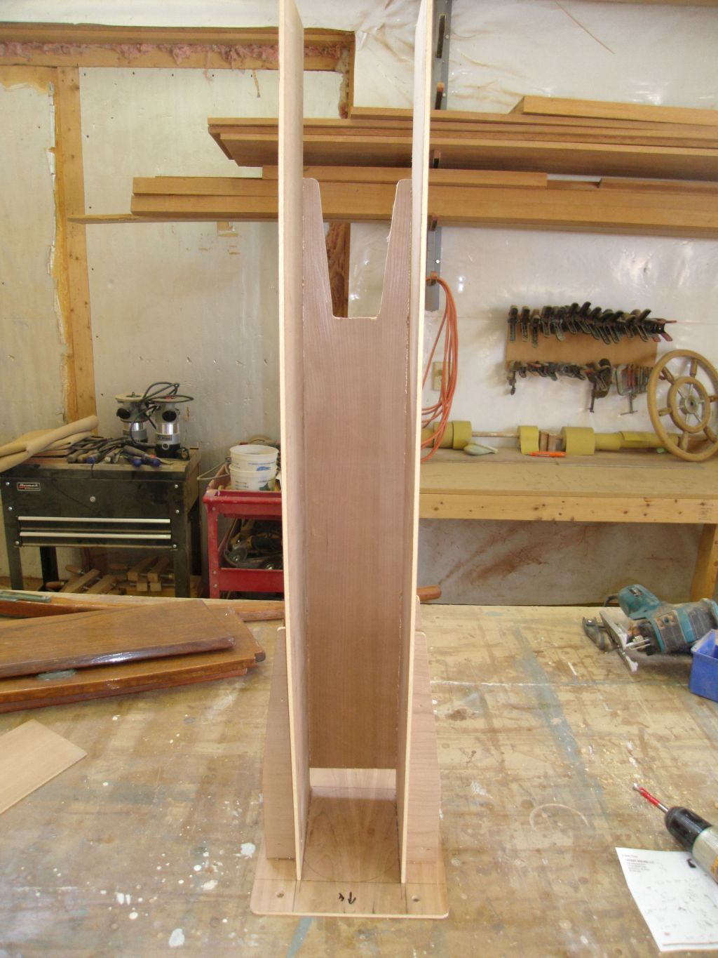
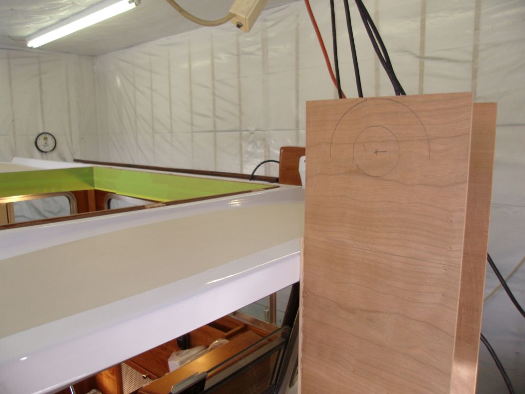
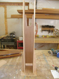
The pivot pin location on the original was 2" below the
top of the 36" tall structure, so for now I replicated
that location. This approximated the height of the
pilothouse, over which the mast would rest when lowered.
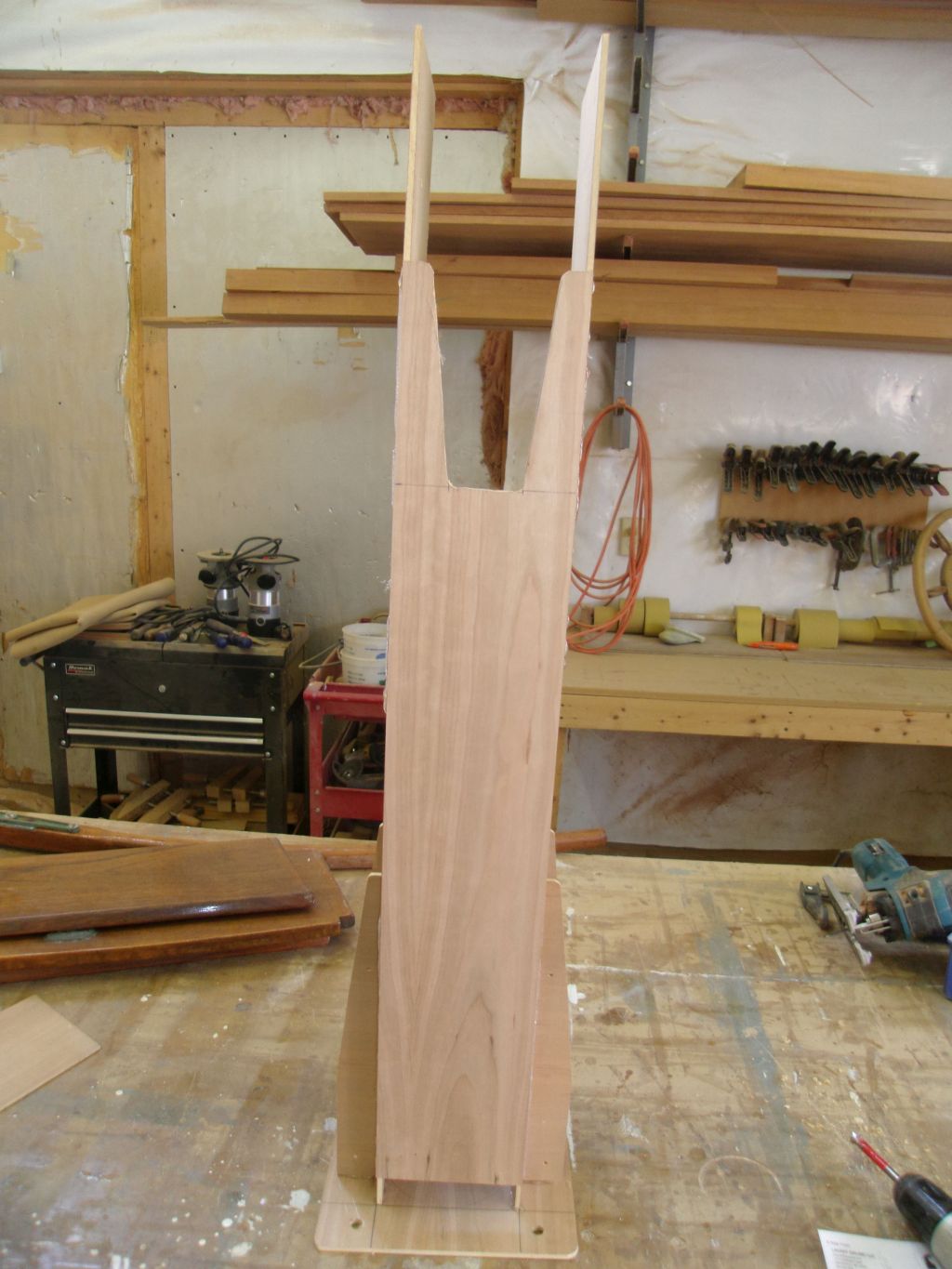
I wanted to do something a little more elegant at the
top of the tabernacle, rather than the boxy original
shape, and I marked out a few potential shapes on one
side of the template, none of which were really working
for me, so, as it was late in the day, I left those
decisions for another time. |
 |
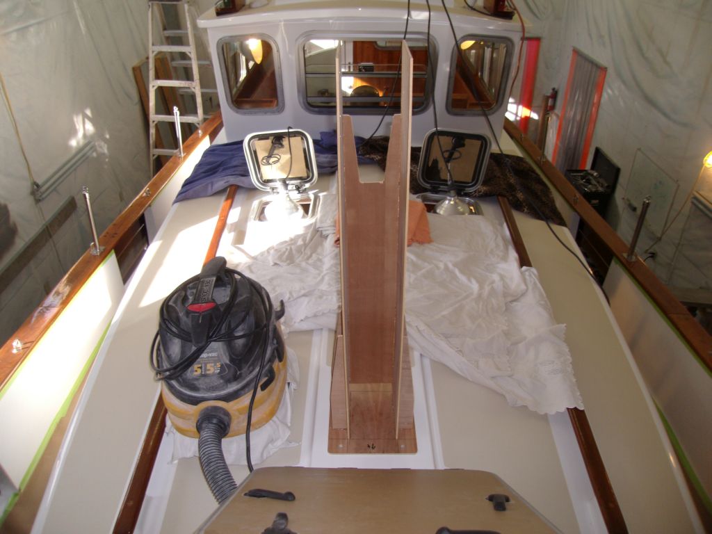
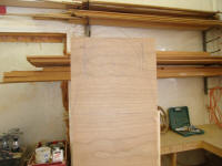
Like my inspiration, I made the base plate a little
larger than the base plate of the original mast step,
but kept the bolt hole locations, since they worked and
would line up with the holes already in the deck, which
I'd left open for this purpose. While the
protrusion was odd-looking without a mast in place, once
the spar was installed it would tend to become
invisible. |
 |
| |
Total Time Today: 4.5 hours
|
<
Previous | Next > |
|
|