Project Log: Saturday, October 4, 2014
As close as the boat was to being "complete", whatever
that actually means, there was still a long laundry list
of woodworking tasks, from the cabin sole to various
final bits of trim. While I was anxious to get
going on these, lest they languish longer, it wasn't a
good time to make dust in the shop, with a painting
project underway in the next bay. So wood would
have to wait.
Choosing a couple straightforward chores on my punch
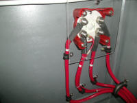
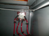
list, I started with the battery switch, which, with its
exposed innards in one of the cabinets, required some
sort of cover to prevent accidental shorting across the
terminals. From clear acrylic, I made a 6" square
panel that more than covered the back of the switch.
Keeping things simple, I secured it over the back of the
switch with the same fixing screws used to secure the
switch from behind. Check.
|
 |
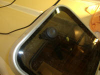
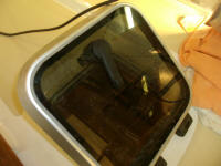
When I purchased the Vetus hatches for the deck long
before, one of the small hatches for the saloon had come
not only with a broken internal handle, but also missing
its top-opening handle (the second one featured this
convenience). At the time, I'd contacted my
supplier, who promptly sourced for me a complete new
operating works for the damaged hatch. While I'd
immediately replaced the broken interior handle, I'd
ignored the top handle till now; it seemed a good time
to change out the blank for a top-opening handle to
match the starboard side.
This proved to be a simple task, and in only a few
minutes the deed was done. |
 |
One problem with a long-term project and numerous
complicated installations, exacerbated by unplanned
delays that stretched completion far beyond what I'd
originally anticipated, was that details of certain
installations became fuzzy with the passage of time.
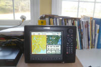
And so it was with the electronics suite, basic
commissioning of which I tackled next since I thought it
would be fun to do, and was also necessary in any event.
When I purchased my system long ago (wow, that was
2011?), I'd set up, in the comfort of my office, the
Simrad display and GPS antenna so I could play around a
bit with the controls and charts and get used to things.
But that was long ago, and I'd never turned the system
on since I'd installed all its various components and
networks. So who knew what surprises might await?
As it turned out, I'd anticipated this, and had made
good notations and so forth in my manuals and elsewhere,
but I didn't know this till I got into the process. |
 |
One thing I knew was that I needed to hook up the radome
before powering up the system, thoroughly integrated as
all the components were. The instructions had made
this clear, and originally I figured I'd have to wait
till the boat was launched and rigged. But now, I
saw no reason why I couldn't temporarily hook up the
radome in the shop, which would be the final piece of
the puzzle required for a test-firing of the system.
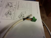
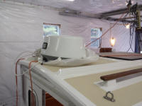
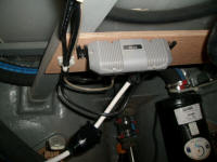
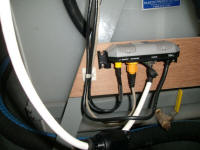
To that end, I unboxed the radome and its network cable,
and, after connecting the dome end of the cable, placed
the dome atop the pilothouse. The other end of the
cable featured four bare wires and an Ethernet plug, and
required some final assembly of the bare wires to a
supplied plastic terminal that would later plug into the
radar's network interface, which I'd previously
installed in the engine room, and to which I'd already
led the required network and Ethernet cables from the
Simrad system. |
 |
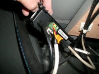
I temporarily connected the two plugs to the network
interface in the engine room, simply leading the cable
through the pilothouse door for now. |
 |
As far as I knew, that was all I really needed to do to
complete the network. But before I could power up,
I had to complete some wiring that I'd intentionally
left disconnected for this very reason: to prevent
powering up before I had all components connected.
During initial wiring stages, I'd left disconnected one
wire from the network interface, though I installed the
required terminal on its end, and also left out the 5
amp fuse in the common power lead for the whole system.
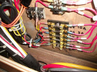
So in the console behind the service panel, I made these
final connections: a brown wire to the left-hand
side of the lowermost terminal on the electronics fuse
block, and a new fuse in the holder next door. |
 |
Turning on the applicable breakers and the main battery
switch, I powered up the system. Nothing exploded,
and generally things seemed more or less OK. But
there were a few little things to deal with.\
Here are a few screen shots showing the most salient
features. I was pleased to find that even inside
the shop, the GPS antenna had found enough satellites
for a fix. |
Left to right: Chart and position; radar; sounder
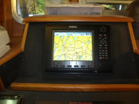
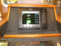
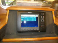
Satellite strength display
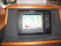 |
When I turned the radar from standby to transmit, after
several seconds I got a message on screen that read "No
Spoke Data", which then changed to "Radar Timeout" or
some such, after which the unit went back to standby.
As of this writing, I'd not yet determined was was
causing this error.
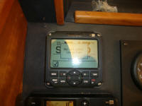
Turning on the nearby autopilot, which had its own
standalone control as well as its integration with the
main display unit, I discovered an error message reading
"No Autopilot Computer". At first, I could
understand what could be wrong there, and was a little
worried about troubleshooting. |
 |
Reviewing the manual, I found a notation that I'd
highlighted during my original installation of the AC12
autopilot computer. The system shipped with its
fuse disconnected, and featured a built-in polarity
indicator to ensure that the power was wired correctly
before the fuse was installed. I'd installed the
wires, but without ship's power at the time, had never
had the system powered up. Of course I'd installed
this well over a year earlier, so I'd not immediately
remembered.
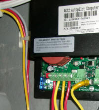
With the power on, I looked in on the AC12. At the
lower left was the fuse, stored temporarily with only
one prong attached. Right next door was the
polarity indicator, as well as the polarity warning
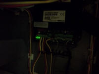
instructions printed right on the case. The light
glowed green, which meant that the wiring was hooked up
correctly. Since it was hard to see with a flash
photo, I took one with no flash to clearly show the
green light. |
 |
I placed the fuse in its proper and final position. |
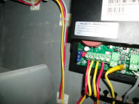 |
This corrected the autopilot fault, though there were
still several additional initialization steps that would
have to wait till later, when I had completed
commissioning of the hydraulic steering system.
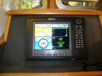
For now, I was happy enough to see the integrated
display on the plotter, seen here in the lower left
quadrant. |
 |
Other than the vexing radar error, for which I'd likely
have to contact Simrad for an explanation, I was pleased
with the initial startup sequence. I played around
with the display for a while, getting re-used to the
controls and various menus and screens. I was
rather bemused to discover that I kept wanting to touch
the screen to make things happen. In 2011, I'd not
yet entered the world of touch-screen phones and
computers, never being one of the first to leap at new
technology (I got my first smart phone sometime in 2012,
long after they'd become well-accepted and commonplace).
But in the three years hence, screen-touching had
obviously become second nature enough for me that I just
tried it naturally and without thinking, though the NSE
8 was not a touch screen device, with most of the
interface working through the rotary knob at the top
right. Still a good interface--just surprising how
one's expectations change with a remarkably short
passage of time.
|
Total Time Today: 3.25 hours
|
<
Previous |
Next > |
|
|


