Project Log: Friday, June
24, 2011
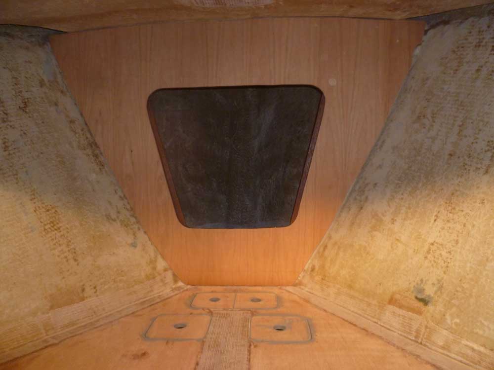
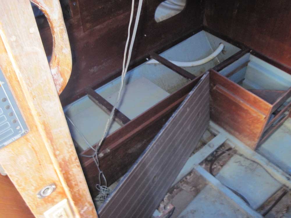
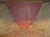
To begin, I finished up structural work in the v-berth
with the usual round of washing and light sanding of the
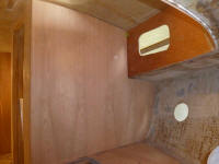
new tabbing. After cleaning up, I installed the
hatches. Sometime later in the process, I'd paint
the platform, but not yet. |
 |
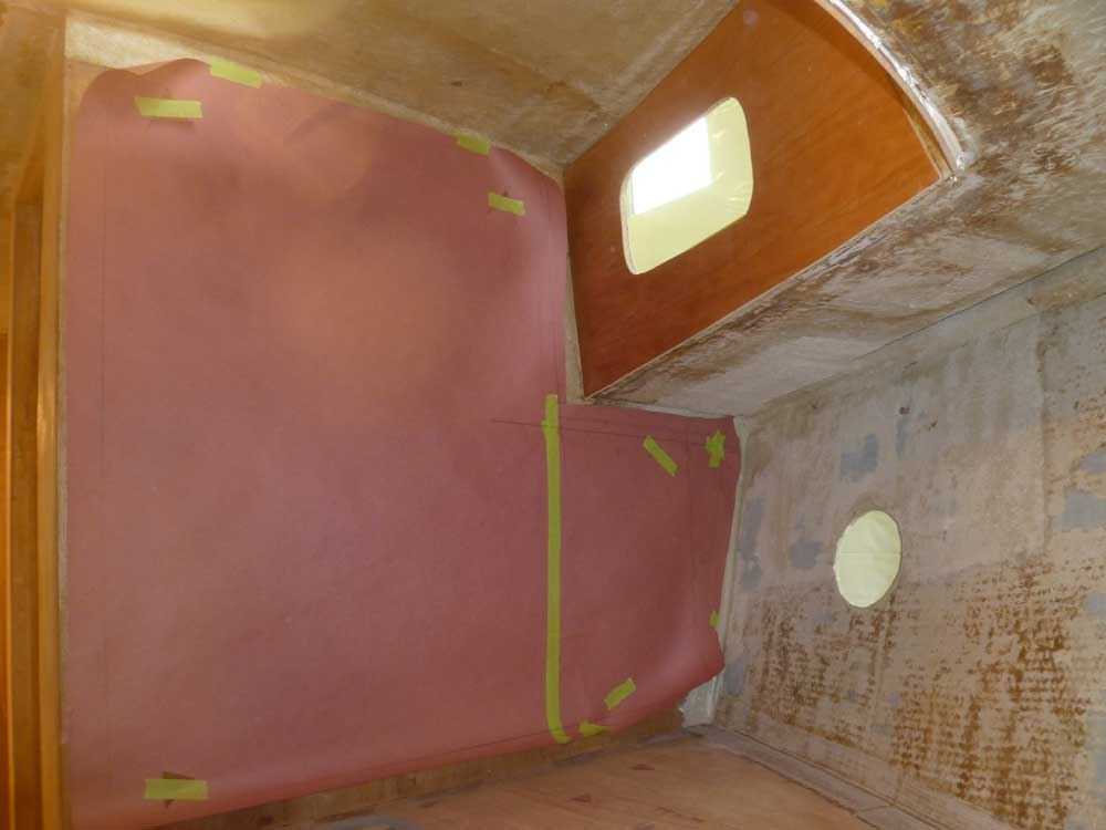
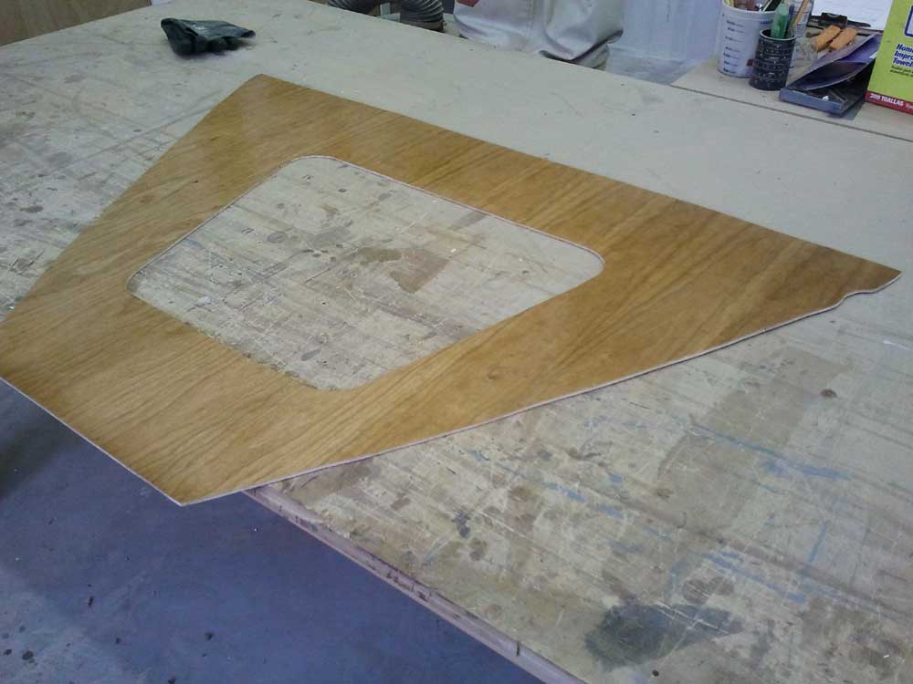
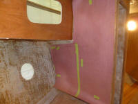
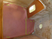
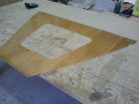
With the platform complete, I could now pattern the
v-berth bulkheads, including the chainlocker bulkhead at
the forward end. Using the leftover paper
templates from the main cabin, I recut them to roughly
fit the bulkheads in the forward cabin, then struck a
pattern line 2" in from the edges using a steel rule and
dividers as needed. |
 |
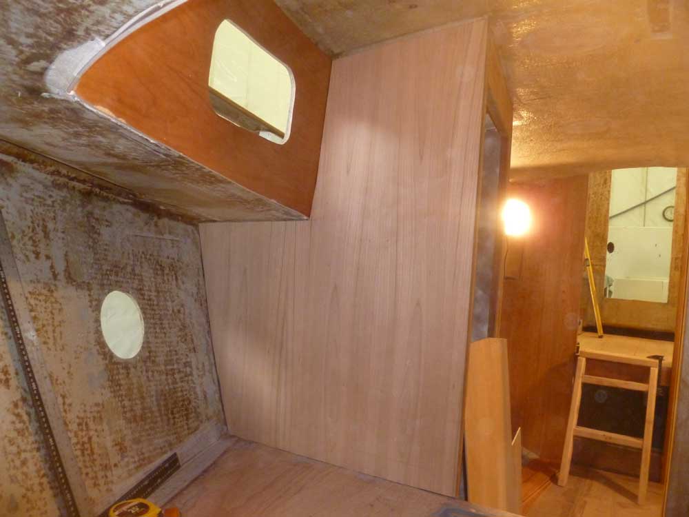
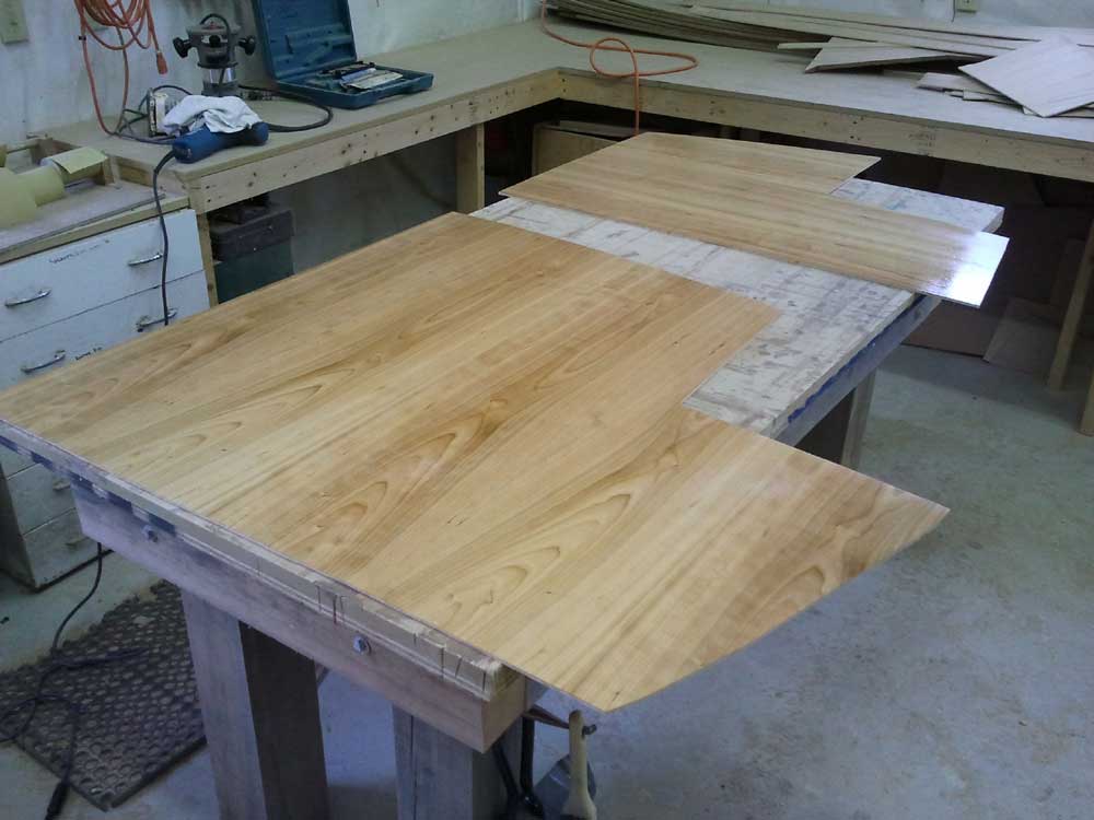
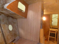
I transferred the patterns to 1/4" cherry plywood.
For the two after bulkheads, I chose my least-favorite
piece of the plywood I had on hand, one with a veneer
grain pattern that I'd earlier put aside for use in
less-visible places. For the chainlocker, I found
a half sheet of cherry left over from some other use in
the past; this sheet had a grain pattern more to my
liking on this bulkhead that'd be more visible from the
after quarters of the boat. |

 |
Thus fitted, I lightly sanded the panels and applied my
usual coat of sealer varnish, setting the panels aside
till later. |
 |
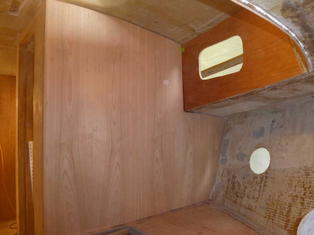
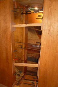
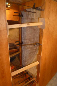
With my work in the forward cabin complete for the
moment, I installed the new veneer in the passageway,
using clamps and cross braces to hold the pieces tightly
in place against the adhesive. |

 |
I debated my next direction for a while, and eventually
settled on the main cabin and the dinette. While
in essence I planned to build a dinette like the
original design, in detail I knew that the original
design left something to be desired (in my mind);
somehow those dead-vertical backrests didn't look very
comfortable. I had some ideas on how to improve
upon that, but the realities of the space would be sure
to complicate the implementation of those ideas.
The only way forward was to try out the ideas and see
how it went. |
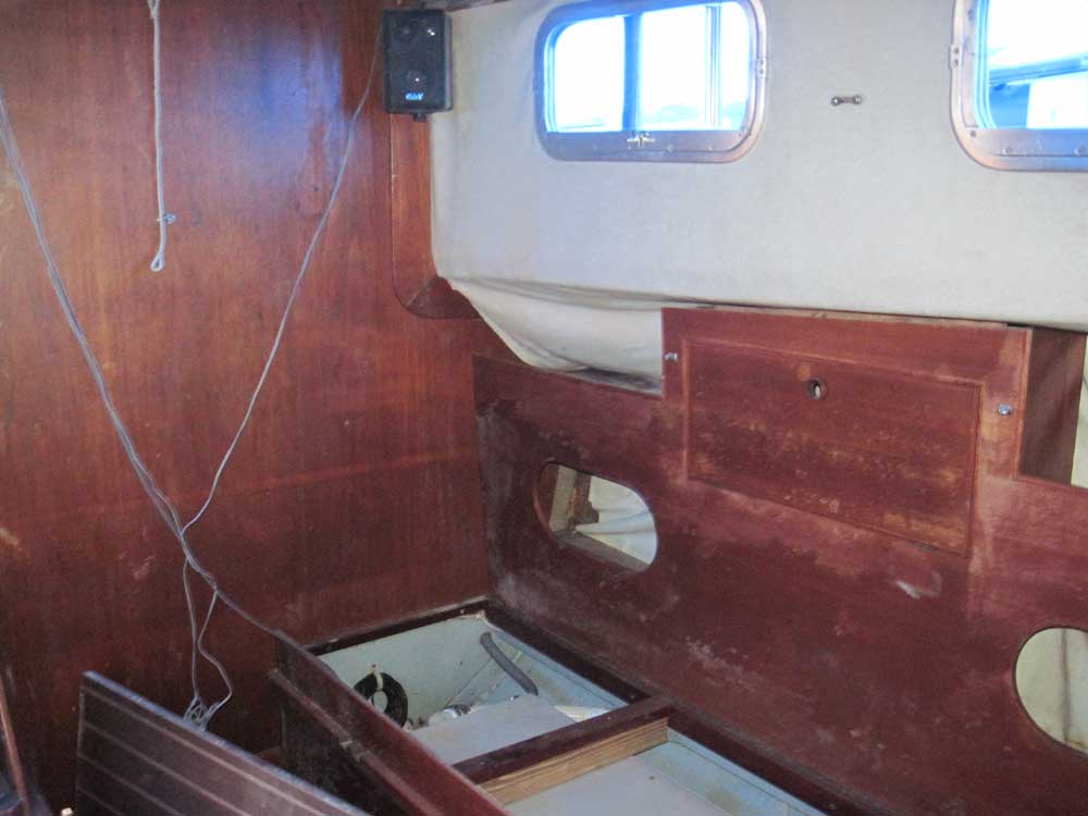
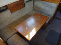
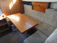
These photos show the original dinette on another Fisher
30.
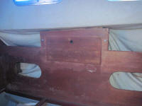
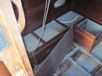
These photos show my original dinette during our initial
viewing in July, 2010.

 |
During earlier stages of the project, I'd continually
made reference marks so that I could relocate the
original structures in the same place, if desired.
Beginning with these basic marks, and referring to some
human design information from my vintage copy of
Skene, plus some ideal dimensional information from
Robert Perry's book on design, I laid out a few marks on
the forward and after bulkheads.
Some ideas I wanted to incorporate if possible:
1. Angled backrest on the long outboard side, and
room for angled back/bolster cushions elsewhere
2. Seating areas 20"-22" wide
3. Recessed vertical panels to allow more room for
heels and feet
4. Ensure that the overhanging cabin trunk didn't
impede headroom while seated
5. Probably a smaller table than original, but not
too small
6. Optimized for two people, but with room for
four to sit comfortably from time to time
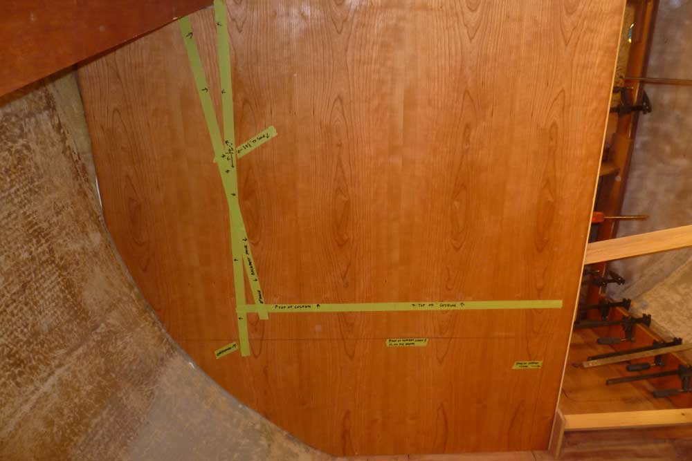
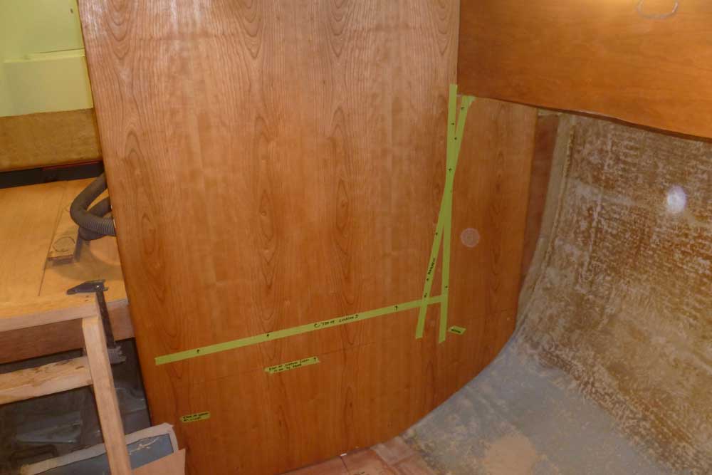
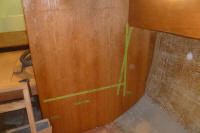
Over a period of a couple hours, I marked out some
basics, including the dinette platform and cleat height
(top of the platform 17" from the cabin sole), eventual
cushion height (4"), ideal backrest location (angled at
10° and keeping occupants' heads inboard of the cabin
trunk), and a few other key measurements. None of
these ideas was remotely final, but only represented a
start towards the final direction.
In these photos, the arrows drawn on the green tape
point to the side of the tape that's representing the
finished surface of whatever component.
As always, click the small photos to enlarge them full
screen. For even more detailed viewing,
click the text links beneath the photos if you're
interested in a full size version that enables you to
read the notations on the tape.
If none of this makes sense, don't worry.
Eventually it will come together into something
tangible. |

Click
this link for a full size version (4320 x 3240) |
Click
this link for a full size version (4320 x 3240) |
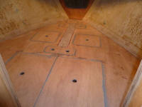
It was late, and I left things at this stage for my mind
to work on overnight. Next, I'd continue some
basic layout and mark out the footprint of the proposed
cabinetry on the sole to help me get a better picture of
the ideas and whether this particular version could
work.
|
Total Time Today: 6 hours
|
<
Previous | Next > |
|
|