Project Log: Saturday, March 5, 2011
I cheated when I decided not long ago to "end" Phase II
of the project and start Phase III. Technically, I
still had two new tanks to install--tankage being of the
main focuses of Phase II. I'd completed everything
but the actual installation of the aft center fuel tank
beneath the cockpit, constructing and installing a new
platform for its support, but had yet to truly address
the forward water tank.
Semantics aside, I next wanted to focus on the
installation of the forward water tank. As it
turned out, this ended up being quite straightforward.
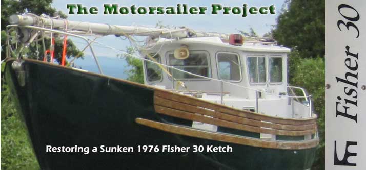
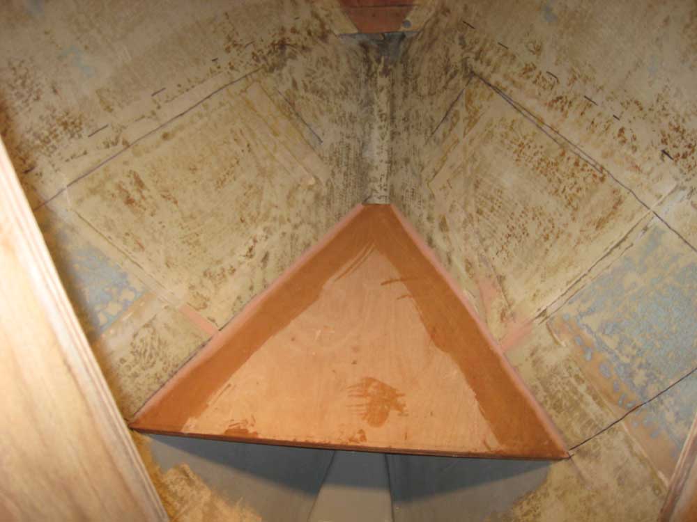
To begin, I drew a level line across the chainlocker
bulkhead, using the shadow of an old support cleat to
locate the line; the old cleat had originally held the
forward end of the V-berth platform, and to the extent
possible I intended to keep the height the same.
From this one reference point, I made a series of marks,
more or less level, along the sides of the hull leading
aft, simply to give me a visual reference for where the
V-berth platform would end up. I needed to know
this so I could ensure that the forward water tank was
properly positioned. |
 |
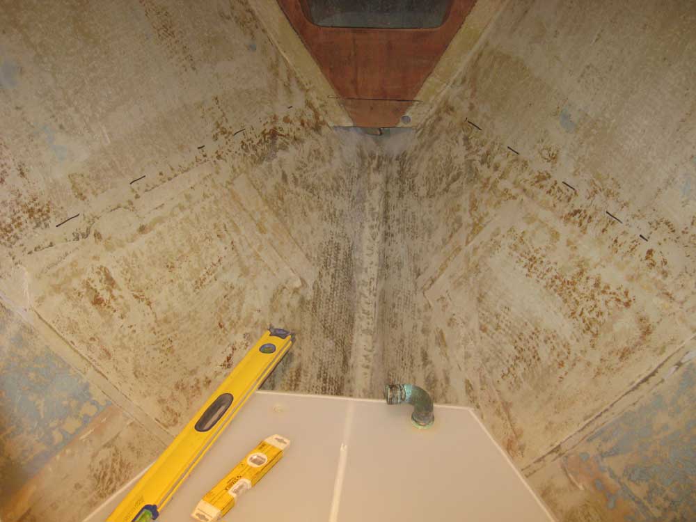
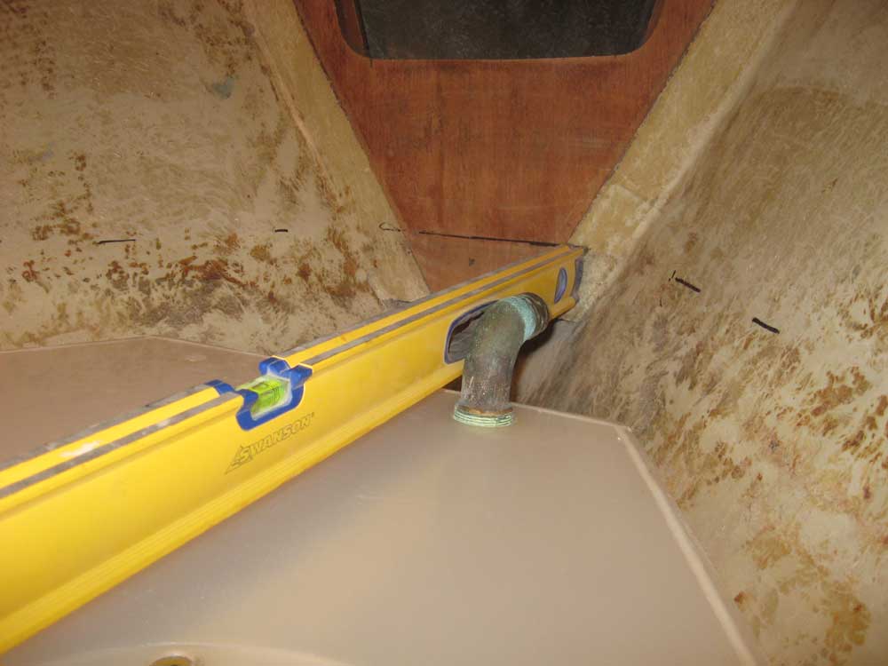
Of prime importance in the tank's positioning was the
fact that I'd redesigned the tank so that all
fittings were on top of the tank, with none entering the
sides. Therefore, I'd need a bit more clearance
above the tank top to allow for the fittings,
particularly a worst-case scenario for the large fill
pipe. To that end, I temporarily installed an old
1-1/2" sweep elbow I had on hand, which represented the
most bulky type of fitting I'd conceivably use.
With this fitting installed, I held the tank in place
against the hull and leveled it side-to-side and
fore-and-aft, then eyeballed the height of the sweep
fitting against the height of the mark on the
chainlocker bulkhead, confirming that the fitting would
be lower than the platform by extending the level
forward. I also allowed space for the hose itself. |

 |
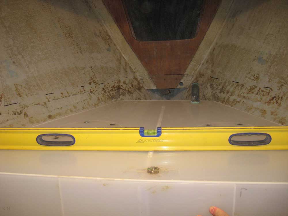
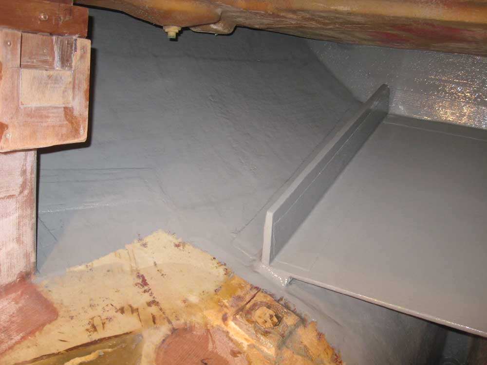
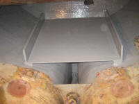
With the tank loosely held in this position, I made a
series of reference marks on the hull so I could
reposition it easily. From beneath, I noted that
the edges of the tank bottom more or less contacted the
hull along their lengths, which meant I could use the
tank bottom as a pattern for a support platform.
While most of the weight of the tank could bear along
its edges, the plastic tank required additional support
beneath to prevent the possibility of distortion, and a
basic support platform would achieve this.
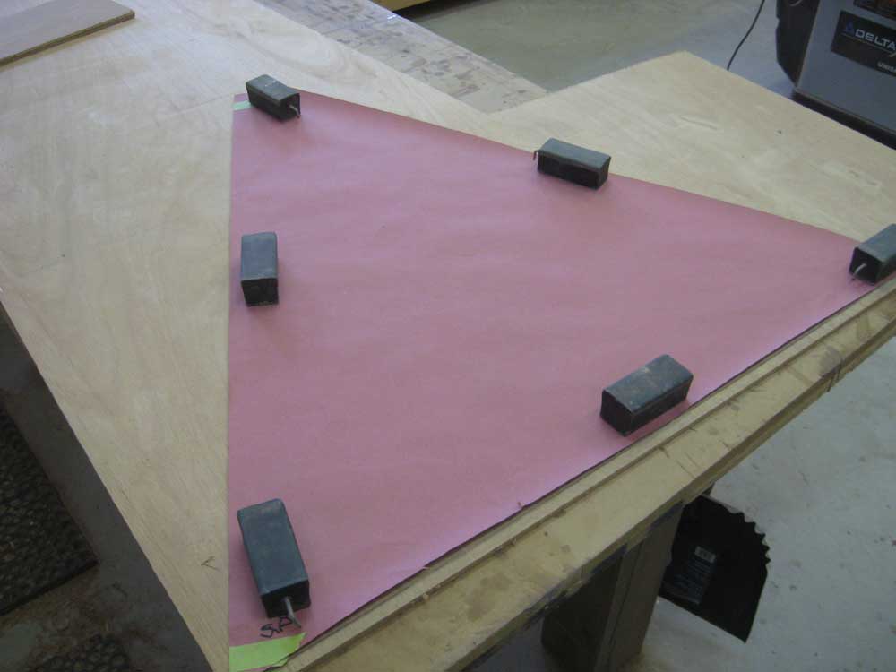
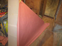
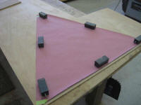
With the tank removed to the main cabin, I created the
paper pattern. |
 |
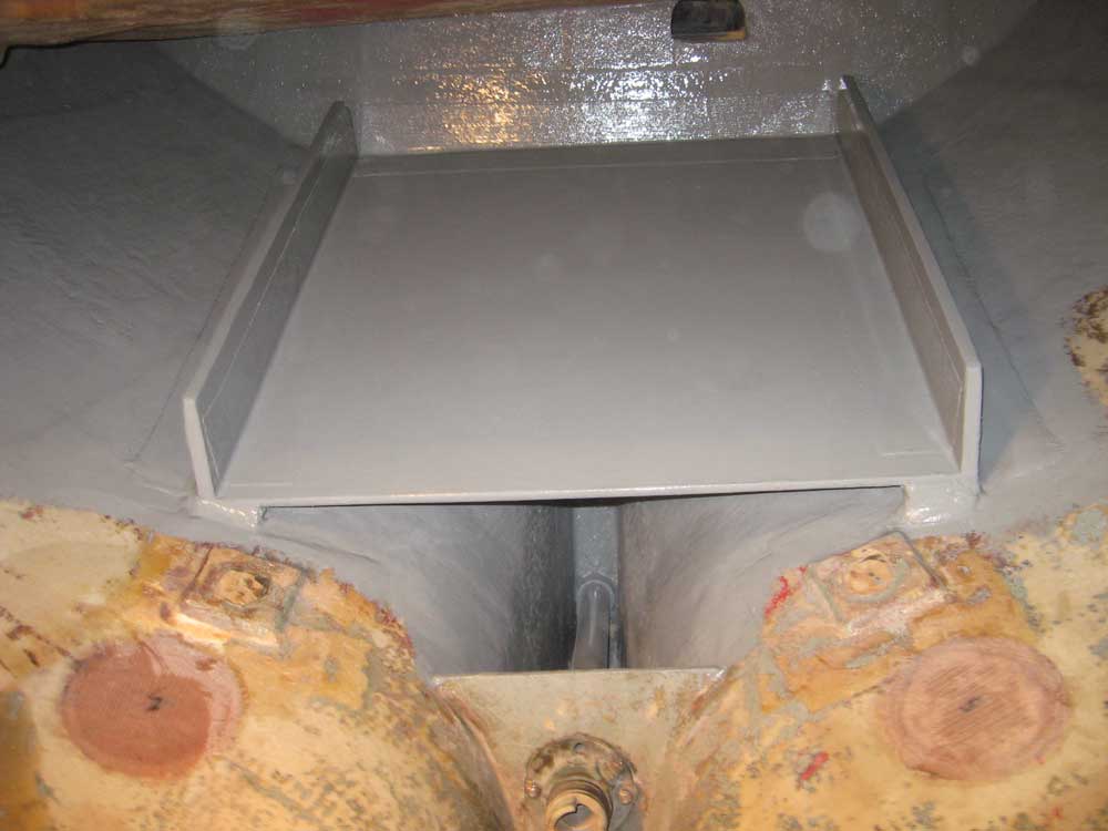
To take advantage of the availability of materials on
hand, I decided to build the platform from two laminated
layers of 9mm Meranti plywood, giving me a total
thickness of 3/4". Using the pattern, I cut out
the first section, adding 1/2" in length at the aft end
to provide a place for an after vertical support
bulkhead to rest later. |
 |
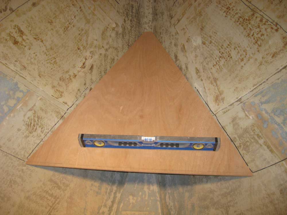
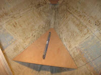
I added the same length to the forward end as well, but
during my test-fit in the boat I discovered that the
platform extended too far forward and wouldn't provide a
natural limber for the passage of water beneath, so I
made a mark on the new platform to reduce its overall
length by about 2" (not shown in these photos). |
 |
Satisfied with the shape of the platform, I used its
bottom edge (the sides were beveled) to pattern the
second layer, which I cut out and then epoxied and
screwed into position, laminating the two layers
together. I held the bottom layer short of the
forward end, partly because that's the width of the
plywood I had remaining, and partly because I saw no
reason to bother cutting an additional piece for the
narrow forward end, which wouldn't require the strength.
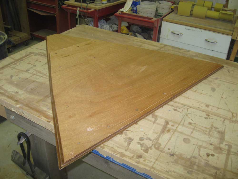
Once the lamination was complete, I applied epoxy all
over the bottom side and edges of the platform. |
 |
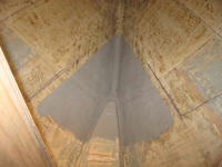
Before installing the platform in the boat, I applied a
coat of gray bilge paint to the space beneath, leaving
unpainted the bonding area near the platform itself. |
 |
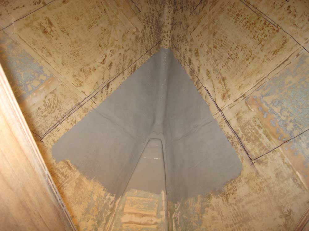
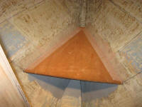
I installed the platform with epoxy around its edges,
and created a small fillet between the platform and the
hull. Once the fillet had partially cured, I
installed 6" tabbing along the edges to bond the
platform securely to the boat, and coated the center
part of the plywood platform with epoxy. |

 |
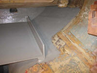
Moving to the engine room, I vacuumed and solvent-washed
the fuel tank platform and adjacent areas. The
epoxy securing the platform had had plenty of cure time,
so it was time to paint out this area, the only task
standing before the final installation of this tank.
I applied a coat of gray paint over most of the area,
leaving a section on the port side aft of the saddle
tanks there, where I thought I might be building a
platform for a water heater, or storage shelves, or
something. Access and available space in that area
was good, which is why I thought it'd be a good location
for something.
The starboard side was laid out differently, with the
closed-off propane locker (original) above, and I didn't
anticipate any installations here, so I painted all the
way to, and including, the aft end of the starboard
saddle tank bulkhead. |

 |
| |
Total Time Today: 3.75 hours
|
<
Previous |
Next > |
|
|