Project Log: Thursday, October 6, 2011
To promote adequate ventilation for the refrigerator in
its enclosed compartment, I needed to provide passage
through the bulkheads and, ultimately, the countertop.
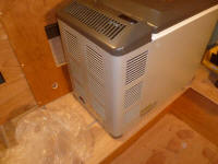
The back end of the refrigerator--the end that would be
against the hull--contained the compressor and numerous
ventilation louvers, so this was the area of the cabinet
I concentrated on. |
 |
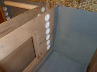
The narrow space between two bulkheads adjacent to the
refrigerator cabinet was a perfect portal for
ventilation. I'd already cut a hole in the cabinet
front for a cherry louvered grill to provide airflow
into and out of the space, and now I installed a number
of round vents in the cabinet behind the range, just to
provide additional means of air ingress, as well as to
promote healthy overall airflow throughout the boat's
lockers. |
 |
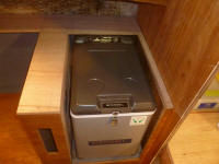
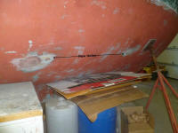
I temporarily slid the refrigerator into its cabinet,
and made some reference marks on the forward bulkhead to
indicate where the side louvers on the refer were
located. I also marked the far extent of the
refrigerator itself, for future reference in installing
power outlets a little later. Sometime later, I
planned to install an additional wooden vent in the
countertop directly above the back of the refrigerator
and its back vents, but I held off till I could
determine the best layout for the upper lockers above
the countertop, which would influence the positioning of
the vent (or vise-versa). The countertop material
was on order, and I hoped it'd be in soon before its
absence led to delays in the continuation of the galley
construction.
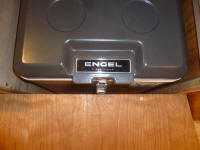
I also found that the additional thickness afforded by
the installation of the galley front gave the refer
latch and handle the extra clearance I needed and that
I'd been concerned about earlier. |
 |
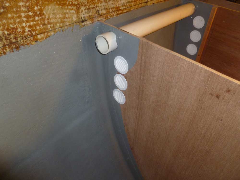
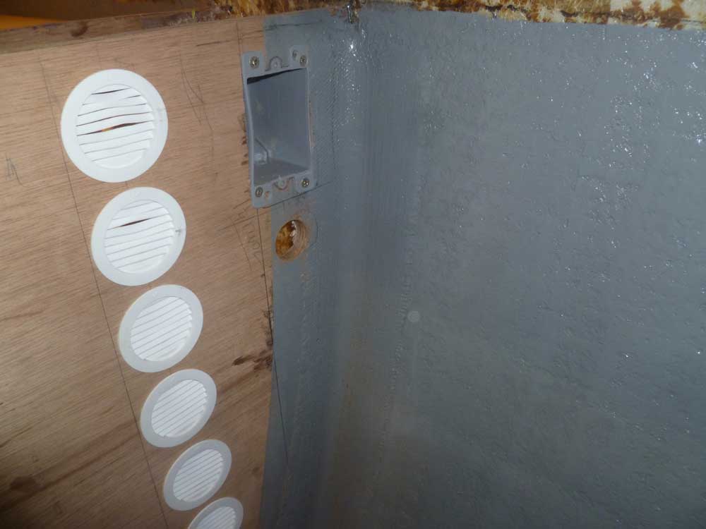
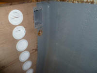
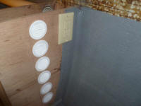
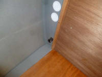
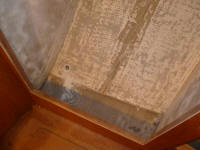
Thusly marked, I installed six louvered vents in the
bulkhead directly in line with the refrigerator's side
vents. Unsure whether natural air flow would be
sufficient, I also planned to install one or more small
12-volt fans (probably computer fans) to circulate air
through the vent system. |
 |
The refrigerator required a means of plugging in, both
for its main power supply off the ship's batteries (DC),
and for AC shore power, should we ever find ourselves in
a situation where it was available. Taking
advantage of the clearest access I'd have to the space,
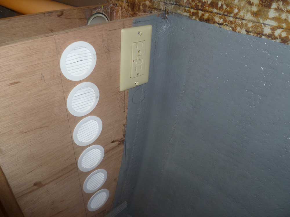
I installed a box for a standard GFCI 120V outlet, plus
a hole for a 12-volt receptacle beneath (the actual
outlet was backordered). I'd install the wiring to
these outlets sometime later in the process; I'd be able
to reach the back sides as needed through my access
hatch in the bulkhead, even when the countertop was
installed. I temporarily installed the GFCI outlet
for display purposes, but then removed it for
safekeeping till it was time to wire it up permanently. |
 |
While access was open, I provided a hole through the
bulkhead behind the stove for the propane supply hose,
and lined it with some rubber hose as chafe protection. |
 |
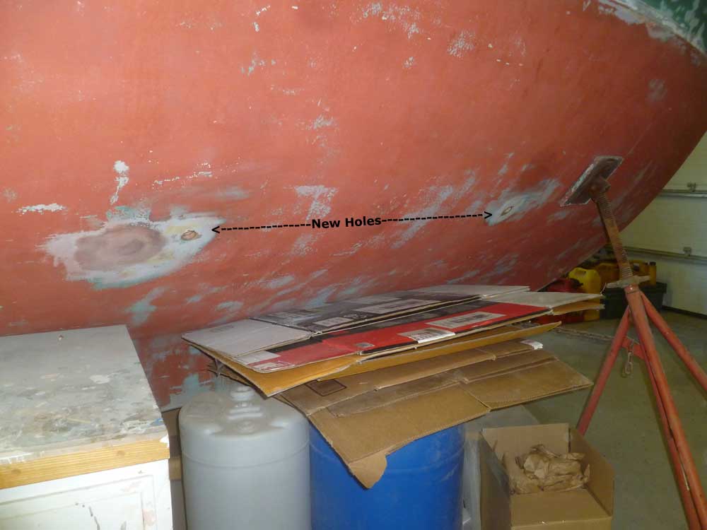
Next, I shifted gears a bit and turned my attention to a
couple new through hull fittings: for the galley
sink drain, which would go somewhere in the galley
cabinet near the sink; and for an additional salt water
intake fitting to service the galley salt water pump
and, ultimately, a deck wash system. I wasn't yet
ready to commit to locations for the other through hull
fittings the boat would need (engine intake, cockpit
scuppers, etc.), but I decided to take care of these two
now since they were in close proximity to one another,
one would be inside the galley cabinet and easier to
install before I closed things in more permanently, and
I liked to install multiple fittings at once so as to
waste as little sealant as possible, since polyurethane
sealant doesn't last long once the tube is opened.
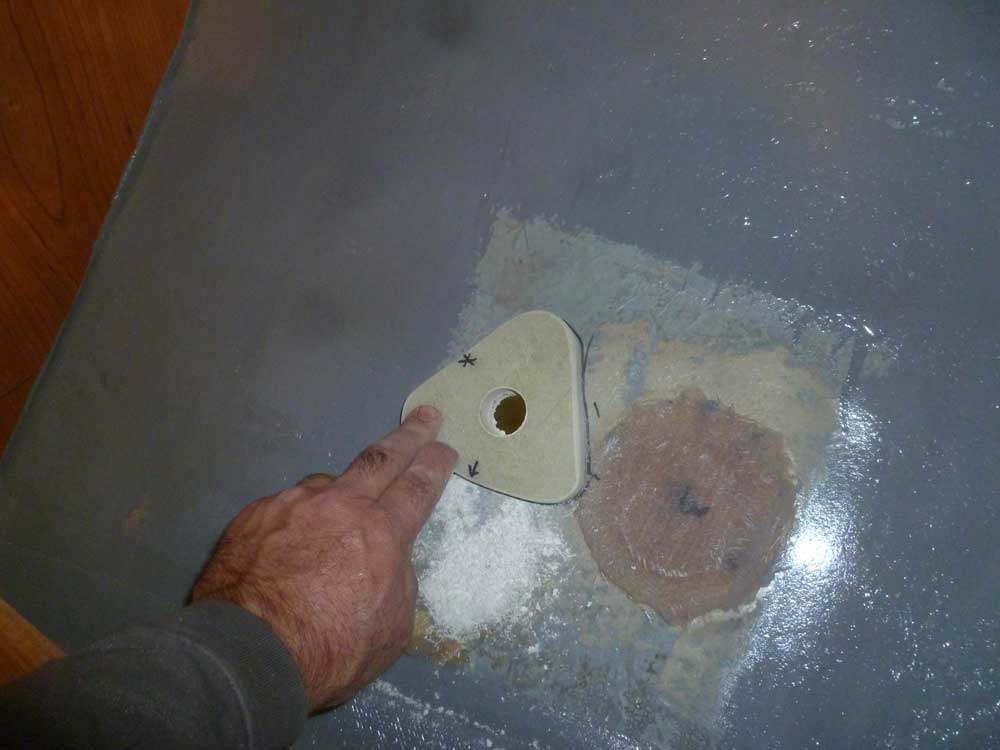
To begin, I cut out a pair of backing pads from 3/4"
G-10 fiberglass, and rounded the top edges and sanded
the cuts smooth. For the through hulls, I selected
bronze flange adapter mount fittings with bronze ball
valves, tailpieces, and mushroom through hull fittings.
With various shelves in place inside the galley locker,
and accounting for other obstructions, I determined the
best location for the through hull fitting, so it would
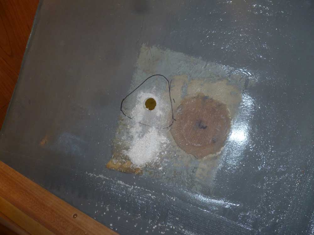
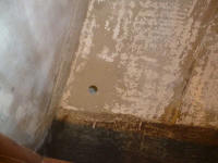
be accessible and convenient. I made sure there
was ample room to operate the valve, twist it on and off
the flange fitting, and other considerations. The
final location was a few inches away from the old
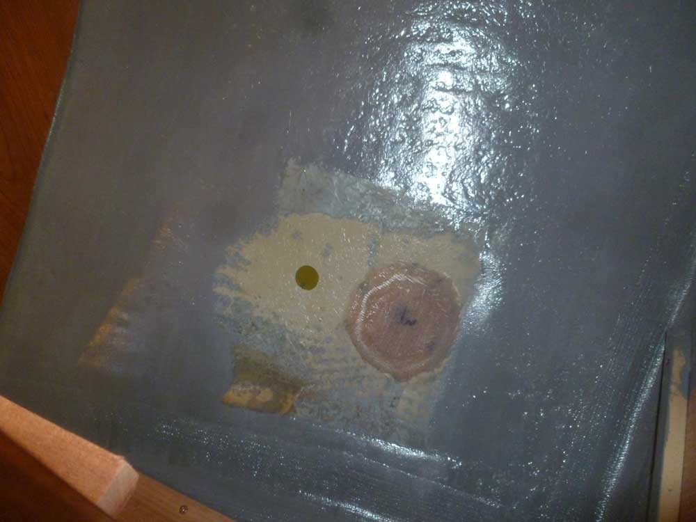
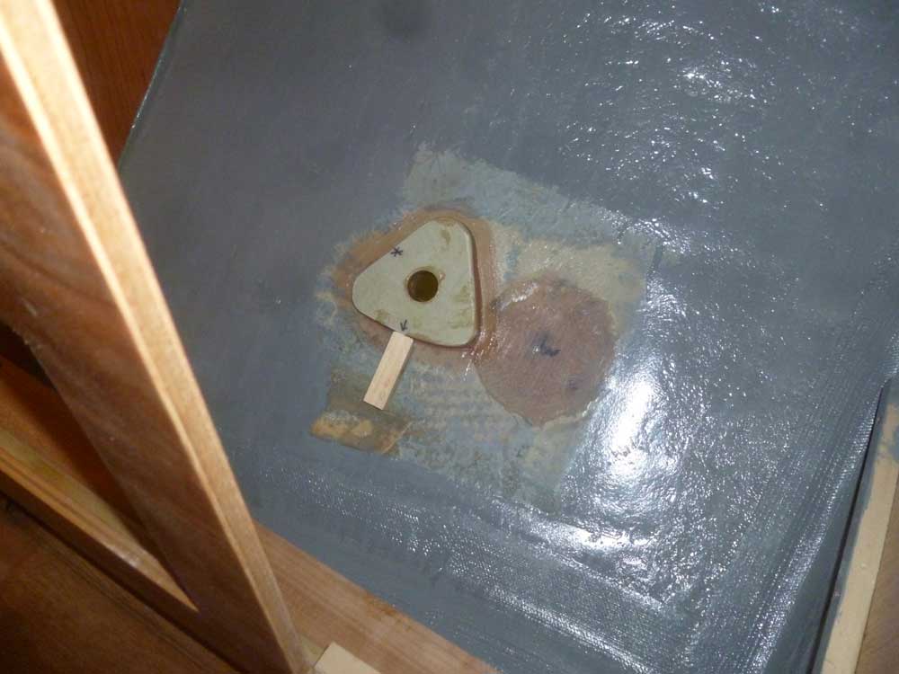
fitting that I'd removed and patched. I drilled a
hole through the hull in the appropriate location, then
sanded away any paint that remained in the area where
I'd be bonding the fiberglass backing pad. |

 |
For the salt water intake, I eventually decided to
install it at the forward end of the hanging locker
(between the galley and the forward cabin). I'd
debated with myself over the need to install a dedicated
fitting for this purpose--versus creating a sea chest to
service multiple needs with a single through hull in the
engine room--but decided that the hose runs would become
unnecessarily complicated and long, and that the extra
fitting would prove to be a much better and more
convenient solution. It was already proving to be
a challenge to route hoses and electrical from the
engine room to the galley, and with limited options I
thought it best to minimize what I actually had to run.
One reason I chose to remove and path all existing
through hulls on this boat was so I could have full
confidence in all through hull penetrations when all was
said and one, so I had no reservations about the extra
fitting.
I chose to install the intake fitting forward of the
sink drain fitting, so that in most situations there
would be little chance of drawing in contaminated drain
water. |
 |
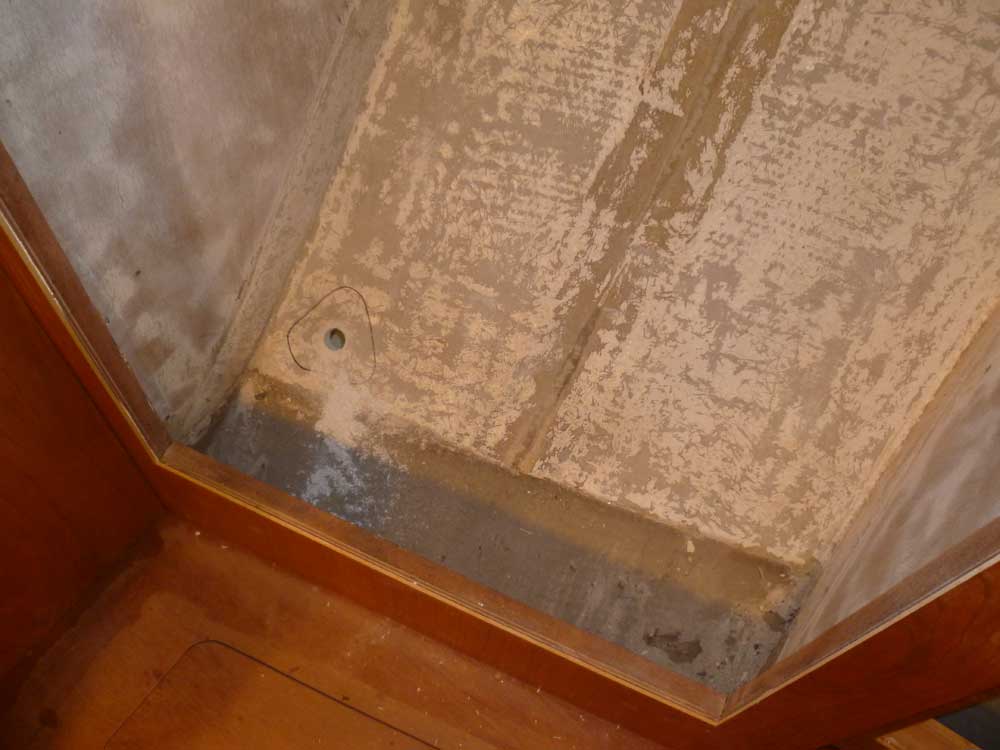
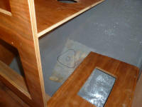
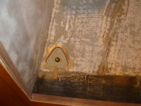
In any event, to locate the fitting in the hanging
locker, I began by deciding, spur of the moment, to
remove a flimsy thin "floor" panel from the original
construction that had somehow survived my earlier
unbuilding efforts. It took approximately 14.7
seconds to remove it and its half-rotten support cleats,
exposing a small remnant of silt-covered hull laced with
hidden grinding dust (which I then cleaned up).
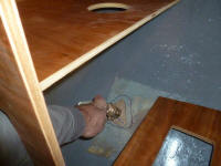
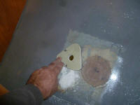
Then, I determined the location for the new through
hull, and marked its position on the hull before
drilling the hole and sanding away the remaining paint
from the bonding surface. |
 |
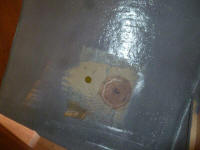
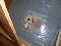
After cleaning the areas, I installed the backing pads
in beds of thickened epoxy. The pads seemed to
want to stay in position on the angled hull, but rather
than take a chance that they'd slip during initial cure,
I held them in place with some scrap blocks hot glued
beneath them. I left these to cure overnight. |
 |
| |
Total Time Today: 4 hours
|
<
Previous |
Next > |
|
|