Project Log: Sunday, August 19, 2012
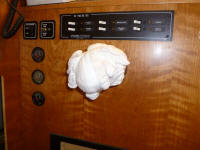
Working while standing on the port side of the engine
room, with the floor removed, meant that the steering
pump was directly at lobotomy level. After three
or four losing bouts with the raw, unprotected end of
the steering wheel shaft, I got smart and wrapped the
thing in a heavy mass of rags. |
 |
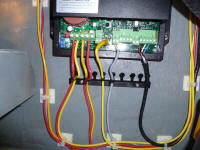
I spent the morning wiring up the autopilot computer.
In addition to the hydraulic pump wiring and steering
feedback sensor wires, I was also required to install
power supply lines and a network cable for the SimNet
system, which would eventually tie this instrument--and
all others--together into a single system.
The wiring was generally straightforward. The
computer featured wire clamps designed for bare wire
ends, so I didn't have to fuss with installing
connectors on the wires (though I think ring terminals
are better than these ones that crush the wire behind a
screw, but I didn't design the computer and greater
minds than mine apparently think this is the best way). According to the wiring
diagram, I installed the various wires in their proper
positions on the wiring board, and secured them to a
supplied strain reliever beneath.
Left to right: power supply (red-yellow);
autopilot hydraulic pump (yellow-red, which are actually
blue-brown in the cable supplied with the pump); ground (yellow);
feedback sensor (gray); SimNet cable
(red-black-white-blue). |
 |
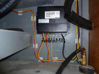
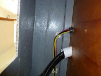
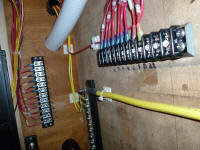
Afterwards, I led some of the wires, as needed, into the
adjacent steering console through a new hole and
conduit. |
 |
Inside, I made up wiring connections to a negative
distribution buss, completing those runs, and positive
terminal block for the positive power supply wire (#22),
which I'd later connect to a main power supply buss.
I left the SimNet cable unattached for now; the other
end of this cable, with its proprietary connector, would
eventually connect to a SimNet connector buss when I
started to lay out that part of the system. |
 |
| |
Total Time Today: 2.5 hours
|
<
Previous | Next > |
|
|


