Project Log: Saturday, January 28, 2012
A month or two ago, I purchased the components for the
new hydraulic steering system. After various
research and correspondence, I selected a Teleflex
Seastar system, upgraded with a brass cylinder (vs. the
stock aluminum) and Kevlar hoses (vs. the stock nylon
tubing). At that time, I'd performed measurements
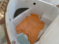
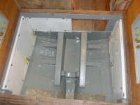
in the after steering room (the cockpit lazarette), and
knew from the onset that providing adequate room for the
hydraulic cylinder would probably require certain
modifications. All of this would also eventually
tie in with my Simrad AP24 autopilot and RPU80 hydraulic
autopilot pump. |
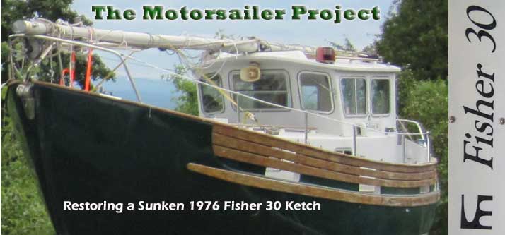
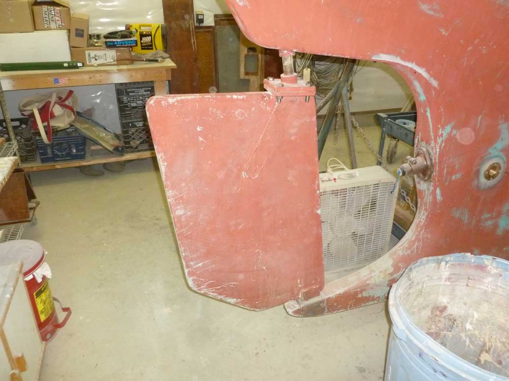
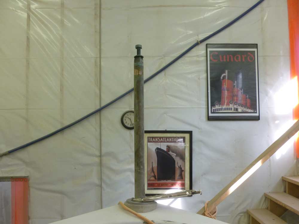
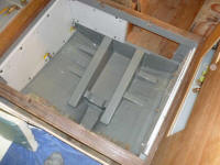
Photo from October 2011 showing the
lazarette opening
 |
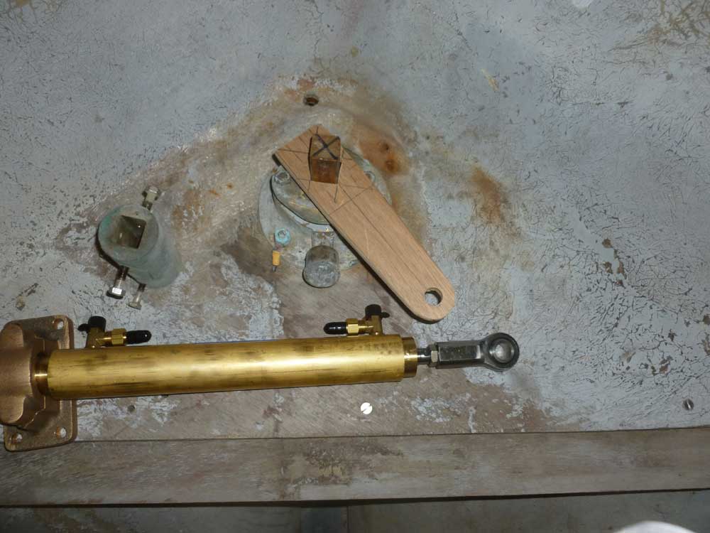
The basic components from which the new system would
grow consisted of a two-piece bronze rudder post; bronze
rudder tube and stuffing box; bronze coupler; and
stainless steel steering arm. The original
cable-driven push/pull steering system had connected to
the steering arm, which was oriented in a transverse
direction facing the port side of the boat. |
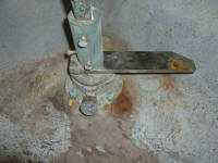 |
Earlier, I'd determined that there was not going to be
room for the hydraulic cylinder with the steering arm in
this position: the fore and aft clearance in the
steering room was simply too short. With more room
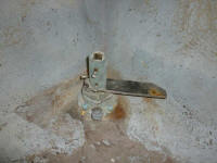
available across the space's width, my first test would
be to move the steering arm's position on the rudderpost
to a different position. At this point, however, I
didn't know if the rudderpost (and therefore steering
arm connection) was round, or squared off.
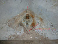
To begin the process, and to ensure that the rudderpost
and all related components would be in their correct and
intended positions, I temporarily reinstalled the
rudder. I love this rudder system, where the
rudder is attached with mating flanges and four bolts:
easy and effective. With the rudder back in place,
I knew the rudderpost components above would be at the
correct height and position, and could also ensure the
rudder's position easily by eye when it became
necessary. |
 |
Next, I loosened the setscrews (a series of hex-head
bolts) and pulled the upper section of the rudderpost
(which extended through the coaming for tiller
attachment) up and out of the way for now, holding it in
place with some locking pliers. I didn't pull it all the
way out because there was a groove with bronze key set
in plate above the coupling, and though this didn't seem
to serve a current purpose I saw no reason to remove the
key either. The key prevented the rudderpost from
sliding through the round hole in the coaming.
|
 |
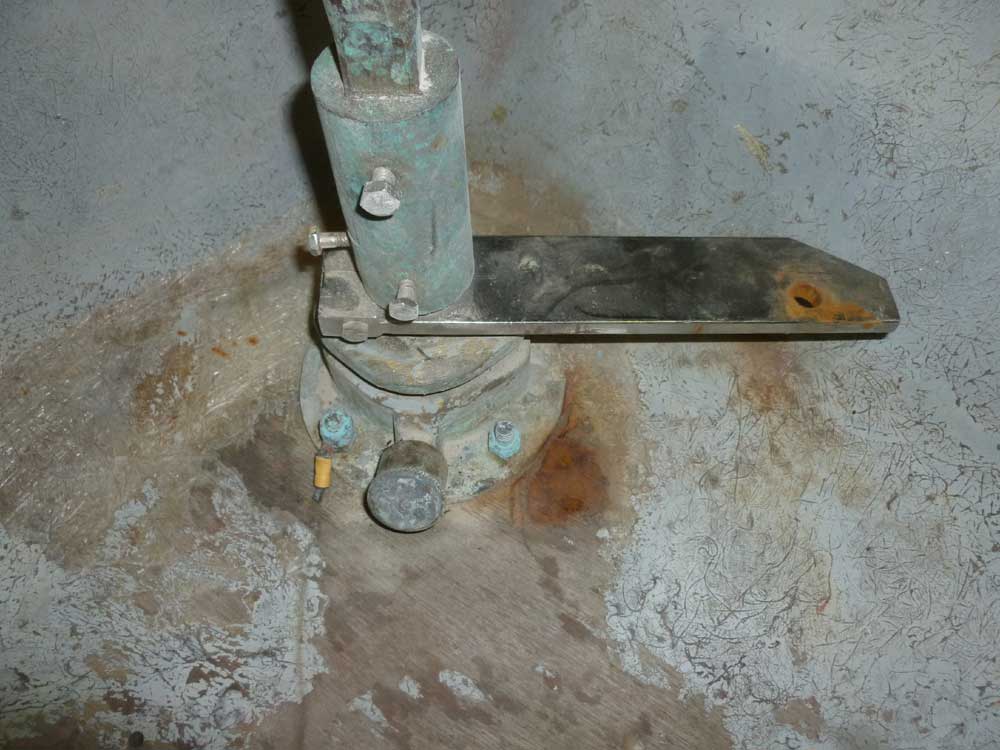
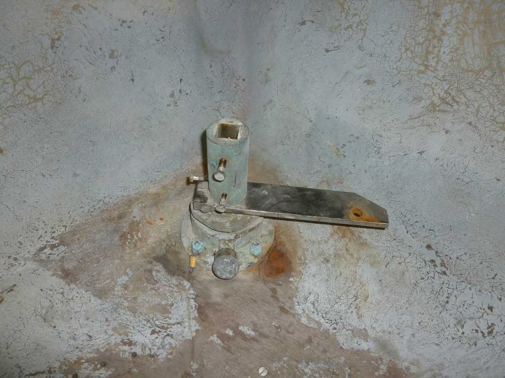
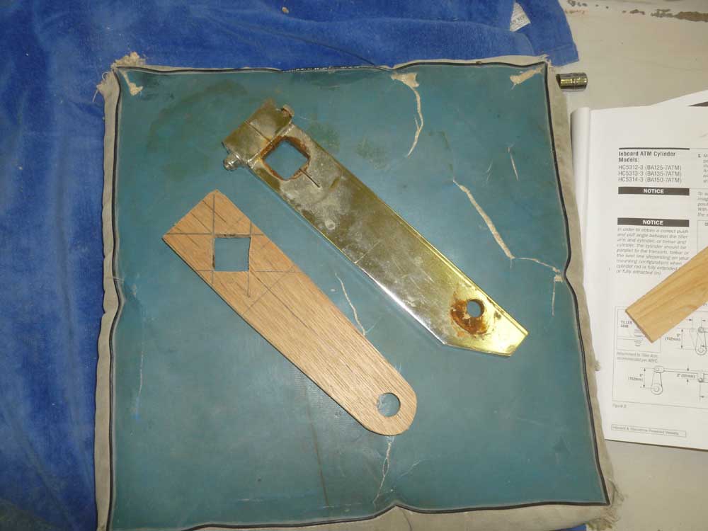
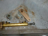
Then, I could remove the coupler, and finally the
steering arm. The rudderpost was indeed squared
off, as was the hole in the steering arm, so whether or
not I could use this arm in the new system would depend
on whether I could simply rotate it 90° and have the
cylinder fit. However, the cylinder, which
required 28" of clearance for full operation, was
clearly too long to fit in this way. This was not
unexpected, though I'd hoped for the easy solution.
I thought rotating the steering arm 45° would work.
So using the old one as a rough guide, but changing the
length and shape slightly, I made a plywood mockup of a
new arm, with the square hole rotated 45°.
According to the instructions, the steering arm should
be 6" between the centers of the rudderpost and bolt
securing the cylinder to the arm, so I made the mockup
in accordance with these instructions. |

 |
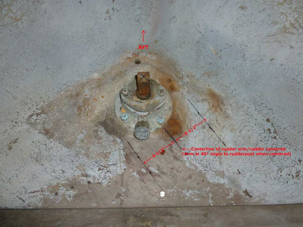
The cylinder needed to be installed parallel to and in
line with a line drawn through two points defined by the
maximum angle of the steering arm, or about 30° to each
side. The instructions called for a 6" rudder arm
(6" from the center of the rudderpost to the center of
the pin securing the cylinder to the arm), with the
maximum angles defined by a 3-1/2" offset to each side
of the center position of the arm. Using the
plywood mockup as a guide, I made various marks and laid
out these key points. |
 |
Eventually, the steering cylinder would align with these
marks, perpendicular to the steering arm and running
forward towards the bulkhead. Even now, the length
of the cylinder and its maximum travel would require
some modification to the bulkhead, but the opening would
end up inside the starboard cockpit locker (which I'd
yet to build). These modifications and final
installation would come sometime later. For now,
I'd determined what I needed and how to proceed, and my
first task from here would be to have a machine shop
make up the new steering arm based on the plywood
mockup, after which I could proceed with final layout
and installation.
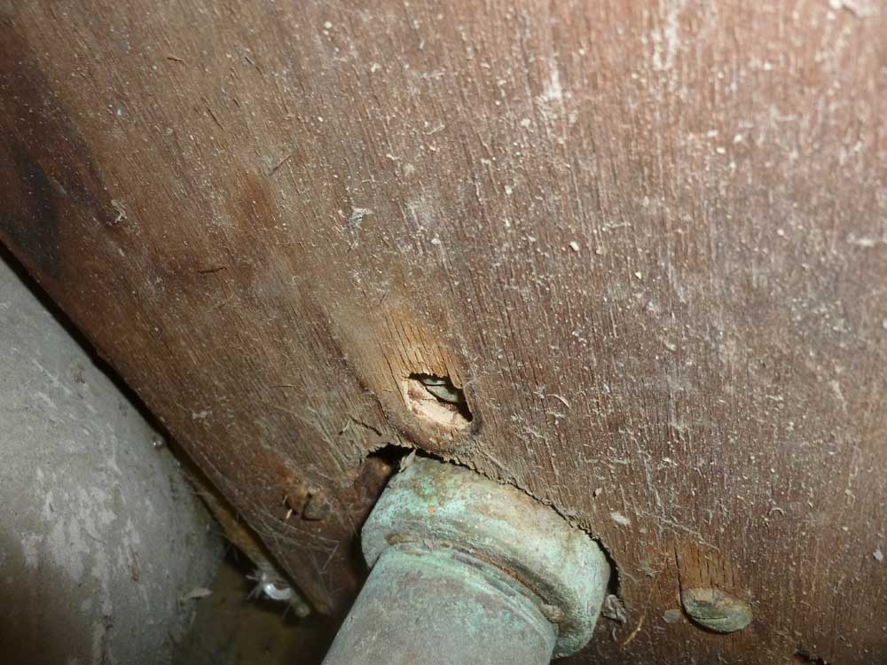
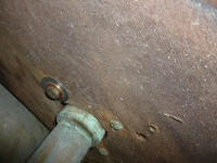
There was an old ring terminal left over from a
now-defunct bonding system secured to one of the bolts
holding the rudder stuffing box to its plywood support
platform. To remove this, I needed to remove an
extra nut that was securing it, but this simple task
turned into something larger when I found that I
couldn't get the nut off the top of the stud; even
holding the fixing nut beneath didn't prevent the screw
from turning, since the action was pulling the screw
head (a panhead, slotted screw that was inaccessible
beneath the platform and visible only thanks to my
camera) into the plywood. |
 |
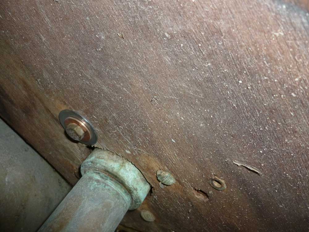
Eventually, with some needle-nose locking pliers that
just fit into the space between the two nuts, I got the
nut and old ring terminal off, but I couldn't leave this
fastener as is. I removed the fixing nut and old
bolt (using the locking pliers to hold the stud) and
installed a new bronze hex bolt with a large fender
washer to protect the bearing surface. |
 |
The after two (of four) bolt heads were completely
inaccessible for all practical purposes, given the
confines of the space and the impedance of the rudder
tube; I was able to tighten the nuts slightly and felt
they were secure as is, so I decided against any heroic
efforts to do anything with them. However, I
thought I might also replace the other forward bolt with
a new one and washers like its counterpart. I made
this decision after reviewing the photos on my computer
vs. the small camera screen, so as of this writing I'd
not yet done the chore.
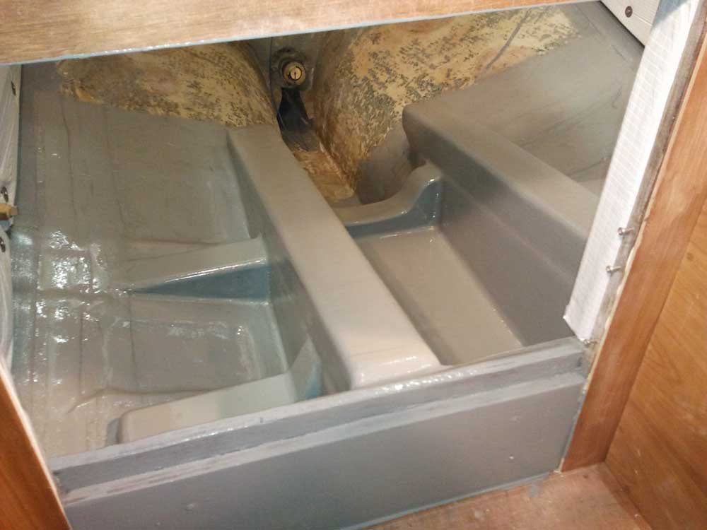
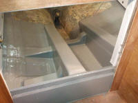
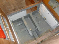
Earlier in the week, I'd painted a small section of the
new engine foundations to test the paint's curing
ability over the relatively new epoxy: Bilgekote,
my paint of choice, will not cure properly if applied
too quickly over new epoxy. Allowing the epoxy to
reach its full state of cure, which can take anywhere
from a couple days to a couple weeks, allows the paint
to work properly when applied. I hoped it'd been
long enough, as I was anxious to paint the engine room
and get ready to install the engine soon.
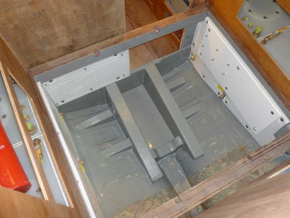
The test patches seemed to have cured completely, so I
went ahead and painted the forward part of the engine
room, as far aft as the ends of the foundations; I left
a section unpainted as I still needed to install some
new through hulls there (cockpit scuppers and engine
intake). The unpainted area wouldn't stand in the
way of other important progress, and in any event I
planned to do the through hulls as soon as I could get
the parts needed. |
 |
I spent the last part of the day making up some orders
for things I'd need for through hull and engine
installation and some other tasks in the coming week or
two.
|
Total Time Today: 5 hours
|
<
Previous | Next > |
|
|