Project Log: Saturday, June 9, 2012
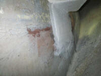
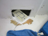
Earlier in the week, I lightly sanded the steering
platform tabbing to prepare it for the work ahead; this
took care of the rough edges and fibers. Then,
later, I applied a coat of high build epoxy primer over
the new fiberglass and nearby fillets. One part
Interlux paints, such as the Bilgekote I planned to use
to paint out the after steering room, have a problem
curing over epoxy that's too fresh, so to get around
this I normally would wait a couple weeks or longer
before applying it. In this case, I knew I'd be
too impatient for that, as I wanted to paint the space
soon and complete the steering installation. The
2-part epoxy primer would provide the required tie coat
to allow me to paint sooner than later. I left the
top of the steering cylinder platform unprimed since it
was unneeded there, and I didn't want to obscure my
layout marks. |
 |
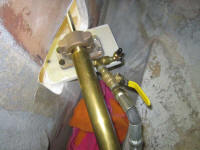
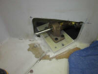
After checking the fit and operation of the steering arm
and cylinder once more, I drilled the boltholes for the
mounting bearing/bracket. The instructions called
for grade 5 bolts, which weren't available in stainless,
so I purchased bolts with a corrosion-resistant black
finish (the same as the ones used by Teleflex to secure
the bearing inside the mount from beneath), the
best option available in the specified grade.
I immediately found that I'd miscalculated the length
required for the through bolts, so I'd have to order
longer ones. For now, I used some regular SS bolts
to secure the mounting base in those areas. The
inboard two bolt locations were inaccessible from
beneath, so I tapped the holes into and through the
fiberglass backing plate for the bolts. I had to
go at a slight angle for one, as the location was
directly in line with the bulkhead above. |
 |
With the cylinder now bolted in place--albeit
temporarily--I checked the operation of the steering
again, looking for any binding or odd noises or what
have you. I was pleased with the operation.
Meanwhile, I prepared for the soon-to-come final
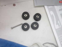
mounting of the hydraulic autopilot pump. I'd be
mounting this on some vibration-damping rubber mounts,
which I lined with SS sleeves to accommodate the 1/4"
bolts. |
 |
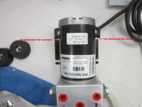
These preparations highlighted what I'd consider
needlessly thoughtless design of the mounting flange on
the autopilot pump. The bolts I specified were
fairly long to pass through the fiberglass mounting
plate and plywood platform beneath (1-3/4" or so total),
plus the rubber mounts (another 3/4"). While the
two mounting holes near the fittings side of the pump
were fine, I discovered that the little brackets
securing the pump itself to the mounting bracket were
partially obstructing access to the bolt holes beneath,
at least from insertion from a vertical orientation.
This meant that it was impossible to set the pump in
place and install these screws one at a time; instead, I
had to insert the screws into the pump mounting flange
first, then dangle them over the holes in the mounting
platform to get them both started. This issue
could have easily been avoided if the mounting bracket
had been just a touch wider, or if these holes had been
1/4" closer to the other end of the pump (and therefore
clear of those plastic pump brackets). The
mounting holes had open slots on the sides, but these
slots were smaller than 1/4" (the diameter of the
mounting holes and bolts), and since the slots opened to
each side, even if they'd been large enough the design
wouldn't have allowed the pump to slip around both of
these semi-accessible fasteners no matter what.
|
 |
This design made it more difficult than necessary to
test-fit the pump, though not impossible. Was I
the only one who found such tiny design flaws so
frustrating and unneeded? This was hardly the
first time I'd found such foolishness, and I could just
never understand why it had to be that way.
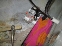
All whining aside, I drilled and tapped mounting holes,
and test-fit the pump in place with its rubber mounts.
I didn't drive the bolts all the way home since I'd be
removing the pump again. |
 |
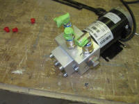
Down on the bench, I removed the plastic blanks and
installed fittings for the eventual hose connections,
covering the openings with tape to prevent any debris
from getting in. |
 |
Thinking through my hose and fitting installation, I
realized that I didn't have the right stuff. The
complication was the shutoff valves that I wanted in the
lines running to the autopilot pump. I'd already
ordered adapters that went from the NPT threads of the
valves to the 9/16-24 compression fitting threads
required for the steering hoses, but what I didn't have
was a means of converting from the tee fittings to the
valves, without using extra lengths of hose. The
tees I had featured three sets of the 9/16 threads, but
I needed one leg to have 1/4" NPT threads.
Fortunately, I found these fittings to be readily
available, so I ordered what I needed. So despite
all my hopes and plans, I'd not be completing the
steering installation this weekend.
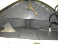
After cleaning out the area with vacuum and solvent
wash, I painted the after steering room. |
 |
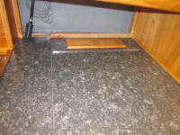
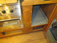
In the cabin, I started work on a few sundry
installations, beginning with two cherry vent louvers in
the refrigerator compartment--one in the countertop, one
in the cabinet face. I'd planned and pre-installed
these earlier, then removed them for final finishing and
safekeeping till now. I installed them with a pair
of screws each. |
 |
I had the vague idea of beginning some water hose runs
so I could install and finish up the galley faucets and
foot pumps, but the day was far too fine outdoors and,
after more than a week of poor weather, I couldn't
resist doing other things outside. |
| |
| |
Total Time Today: 3.25 hours
|
<
Previous | Next > |
|
|
