Project Log: Saturday, March 17, 2012
I spent most of the day working on the dashboard and
companionway trim. What initially seemed a
straightforward task of cutting and fitting turned into
a little more, but ultimately for the better.
Sometimes, how one expects things to proceed turns out
to be wrong.
Ideas and expectations are continually under advisement
and subject to changes. Most would prefer you not
know about it, but to me this is the most instructive and
realistic part of the process. You, dear reader, get to
share in the entirety of what a job like this entails
from time to time.
Having already learned lessons from the single piece of
the dashboard fiddle I'd installed last week, this time,
instead of laboriously notching the trim over the couple
obstructions in its way (the side of the helm console
and the starboard side bulkhead), I chose to simply cut
down slightly these obstructions so the trim could pass
unimpeded above. The angled helm console side was
simple to cut with a Japanese-style saw, and I just
notched out the plywood bulkhead with saw and chisel in
the appropriate place. This made fitting the trim
much simpler.
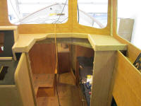
The problem, as it were, was the 90° corners leading to
the companionway opening. As I started to lay out
the first piece, leading from the helm console towards
the companionway, I realized I didn't want a typical
miter joint with its resulting sharp corner there.
This brought the process to a halt while I considered
what to do instead.
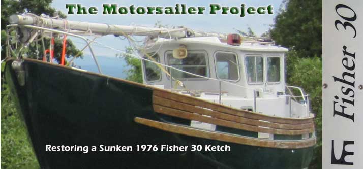
Eventually, I decided to build some solid corner
blocks, into which I could incorporate a large radius
that seemed better suited to the location. Then,
I'd simply butt the fiddle trim into the corner block. This
was simple enough, but building the piece required a
number of milling steps to properly size the blank,
round over the outside edge, and notch out the unseen
inside portion so the piece could wrap around the corner
as needed. I left the dimensions of the corner
blocks just slightly larger than the fiddle trim, so the
blocks would stand a little proud and look intentional.
"If you can't hide it, highlight it".
With an overlong blank of the trim held in place, I cut
the adjacent pieces of fiddle to the proper length, then
cut off the trim to the proper height. This
revealed a new problem: there was an empty square
hole formed behind the corner, where the corner trim was
notched out and behind the inside corner where the two
pieces of fiddle met. Sigh. I was flummoxed.
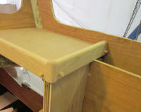
My solution was to cut the corner trim a bit short, then
add a solid wood cap that I milled with a rounded
profile and intentionally left high of the surrounding
trim to create to tiny pillars (or maybe tiny newel
posts). Trying to incorporate all these pieces
into a smooth, organic, nearly seamless transition could
have been possible, but was beyond my level of interest.
In the end, I was actually quite pleased with the
result, so perhaps I should have suggested this was my
bold intent all along. Alas, the secret is out. |
 |
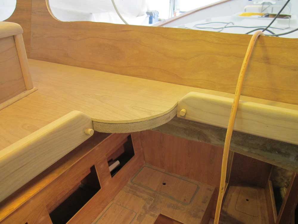
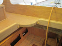
With the too-complex simple corners complete, the
remainder of the companionway trim was quite
straightforward to install, though carefully fitting of
the various pieces, all of which met at various mitered
angles through the inside corners of the opening,
required numerous trips up and down to cut and fit each
piece properly. Where the fiddles met the round
corner block at the compass location, I allowed the trim
to angle down and die out at surface level. |
 |
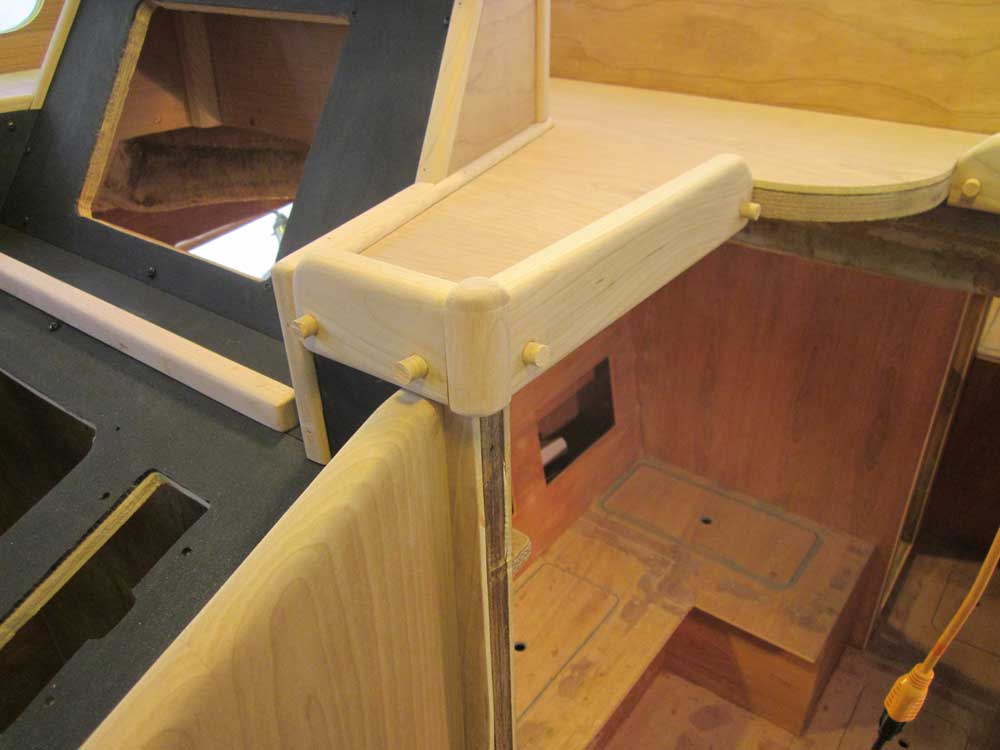
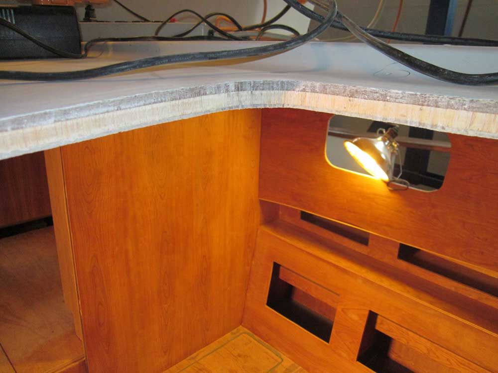
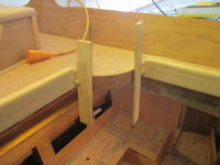
For the rounded section, I needed to curve some wood
around to cover the plywood end grain. I planned
this trim to be flush at the top edge, partly because
creating tall, thick trim like that of the surrounding
fiddles seemed a complex problem, and partly because the
flat area, with the compass set back 1/2" from the side,
would give me a space to more easily clean out the
dashboard; such openings in fiddled surfaces are crucial
for sweeping away routine dust, etc. with less
frustration.
To this end, I cut a slim piece of solid cherry that I
thought I could soak in hot water and bend into
position. After soaking most of the afternoon, I
found I could bend the trim into place quite easily.
Initially, I planned to temporarily screw the wet trim
into place, to hold it while it dried--and did install a
screw in the center--but I found that the
as-yet-untrimmed bungs at the ends of the nearby fiddles
made perfect wedging locations to hold the ends of the
curved piece in place, obviating the need for screws. |
 |
Depending on how the piece acted when it was dry, I
thought I might cut and soak a replacement piece and
wedge it in this manner, avoiding the use of fasteners
at all. More on this when it happens.
I prepared some trim blanks for the top edges of the
longitudinal plywood bulkheads on each side of the
pilothouse, and was well into the process by the time I
discovered that one of the pieces had a split at the end
that extended too far into the blank for me to cut out
and have enough length remaining. I decided
against continuing for the moment, and instead decided
to prepare some holes in the deck for new hatches in the
main cabin.
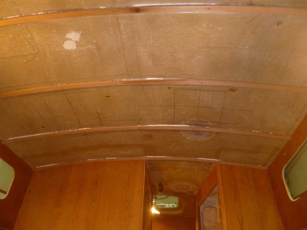
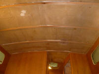
Earlier, during my layout for the overhead support
cleats, I'd planned out the locations for these hatches,
though at the time I'd not yet decided on the exact
hatch I'd use, though I knew they'd be the 12" square
variety. In the time since, after looking at all
the hatch options available, I selected Vetus Magnus
hatches, which seemed a fine combination of good
appearance, strength, features, and price. I
wanted to cut the openings and dry-fit these hatches
sooner than later so I could install additional overhead
cleats as needed, and also to determine if I needed to
build any risers to support the hatches (depending on
whether the deck was curved enough to require it). |
Photo from 12/18/11
 |
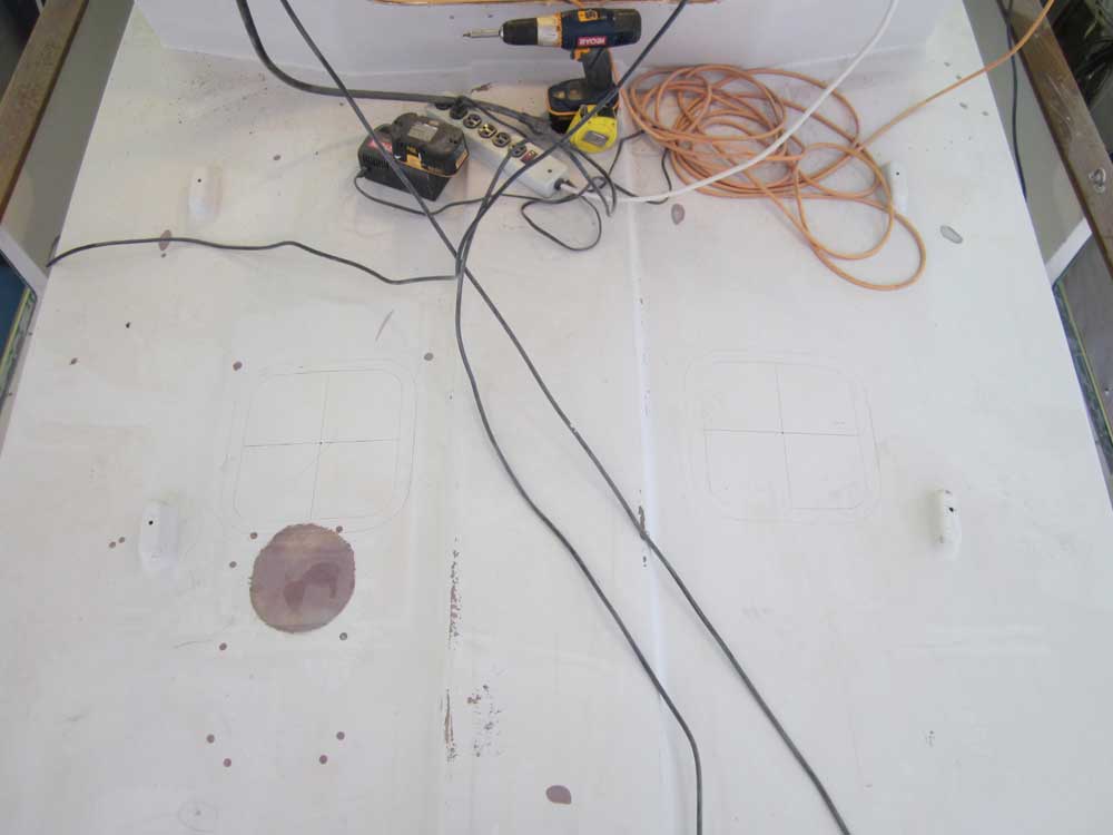
Armed with a cardboard template I made of the hatches, I
started from below and centered the template in the
rough square I'd laid out during the overhead cleats'
installation; I'd marked out a square that represented
the maximum overall size of the hatches under
consideration. The Vetus hatch was a bit smaller
than this maximum, so with the template aligned to the
center marks of the rough layout, I drilled a pilot hole
through the center of the cutout square so I could
locate the hatch from on deck.
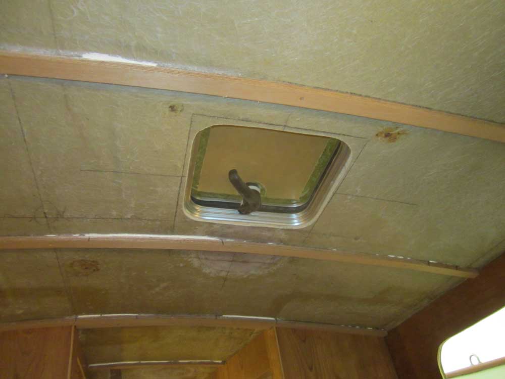
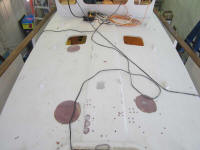
Thusly marked, I returned to the coachroof and used the
center pilot hole to align the cardboard template and
trace around for the cutouts. |
 |
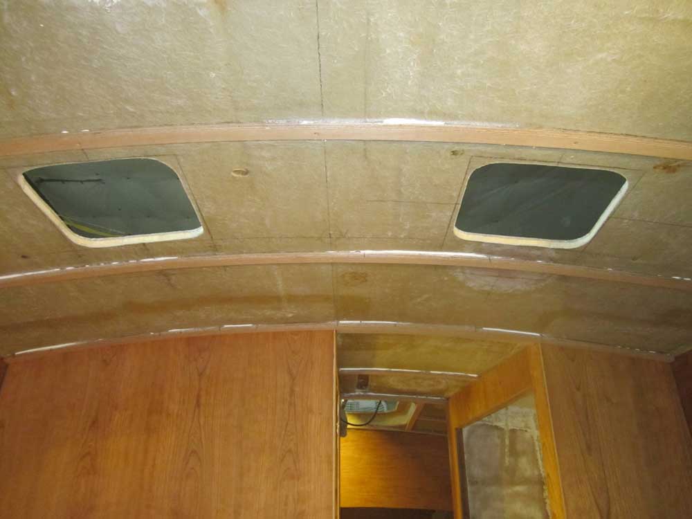
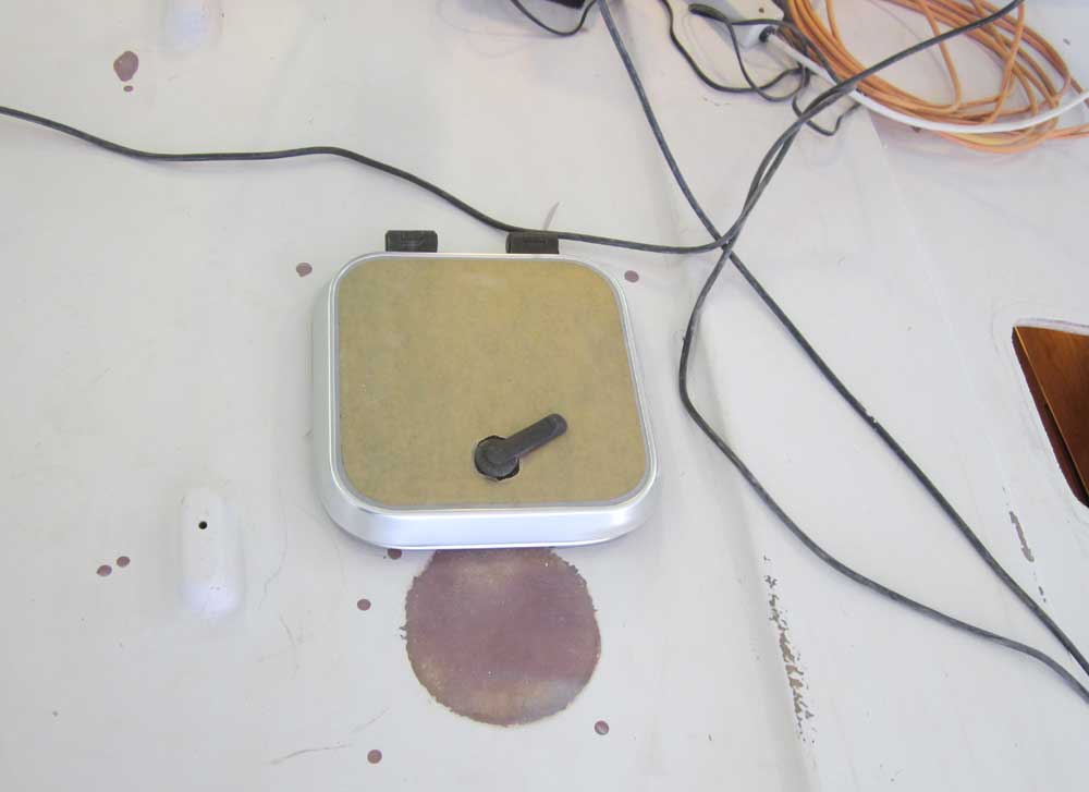
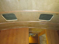
Finally, I cut out the rough openings with a jigsaw and
a carbide blade. The decks and core were in excellent
condition in this area; later, I'd dig out the core
around the edges of these openings and replace it with
solid material. |

 |
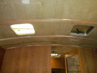
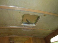
Note: the hatch has protective paper over the
acrylic lens. |

 |
Total Time Today: 6.75 hours
|
<
Previous | Next > |
|
|