Project Log: Friday, May 8, 2015
Though I'd made good progress through the week, most of
the jobs had been hampered somewhat by a continuing--if
not necessarily surprising--need for different or
additional pieces and parts: the scourge of the
punch list. My Projects, Interrupted list
included the electric bilge pump installation; manual
bilge pump installation; saltwater washdown system; and
mizzen mast wiring. But new deliveries had rounded
out the materials inventory, and I couldn't wait to get
back to these several items and fully complete them.
First on the list: the saltwater washdown.
The new 316SS pipe nipple (1/2" NPT male pipe threads to
3/4" hose adapter) had arrived, and with no further ado
I installed it to the base of the deck hose fitting and
secured the hose, completing that installation.
|

 |
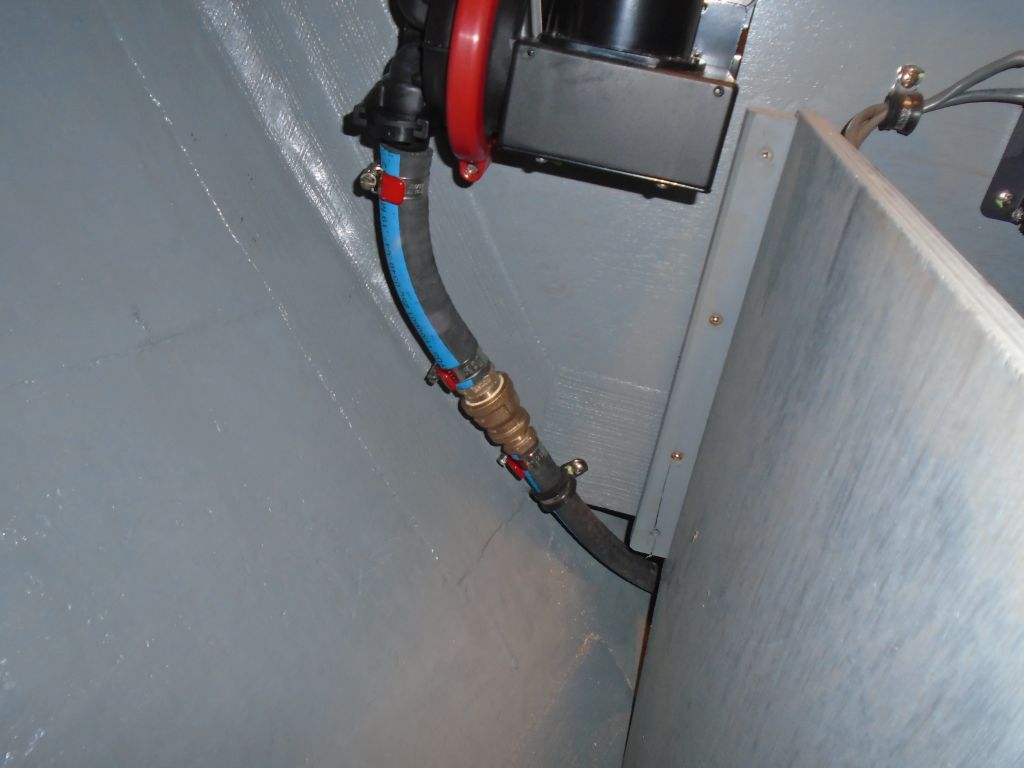
To complete the two bilge pumps' installation, I'd
required some different hose for the electric pump
(1-1/8", now on hand), plus different bronze adapters
for the discharge (since I'd originally planned--and
purchased for--3/4" hose). To begin, I
pre-assembled a bronze tee, 1-1/2" hose adapter (for the
manual pump), and 1-1/8" bushing and hose adapter, then
spun this assembly onto the new discharge through hull
in the lazarette. |
 |
With my messenger line in place, it was pretty quick to
pull the new 1-1/8" hose into the bilge, where I
attached it to the pump and secured it as needed on its
run aft, to keep it clear of the shaft. |
 |
When I ran in the new hose, I also ran in a new length
of messenger line, which someone might thank me for
someday. I secured the ends in the engine room and
lazarette as needed. |

 |
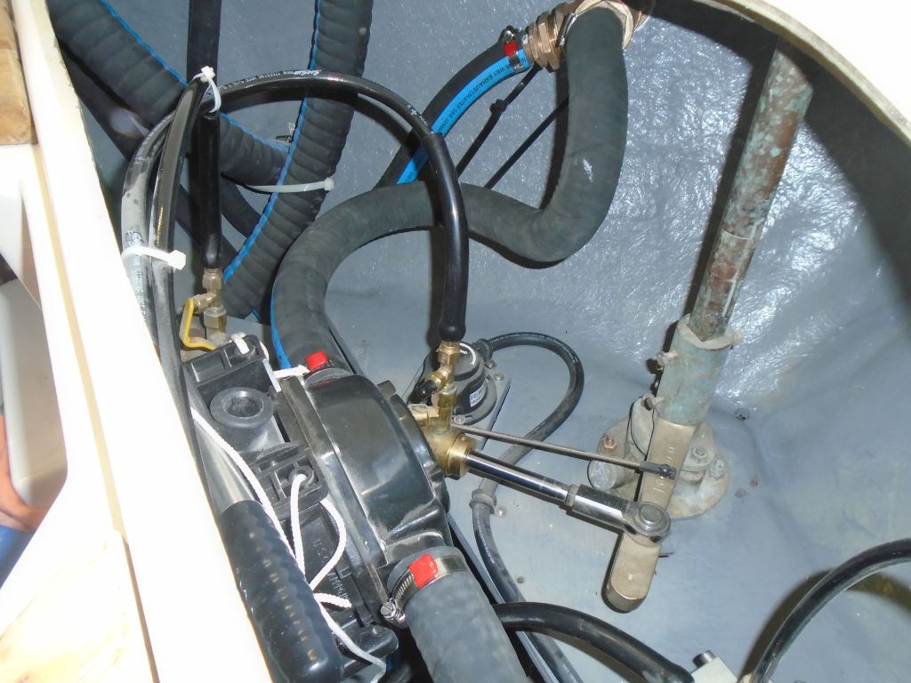
I completed the electric pump's hose run by leading the
hose into a loop above the discharge, then connected it
overboard. While the high loop increased the
pump's head, which would reduce its capacity, since the
electric pump was just for convenience and reduction of
nuisance water, I didn't see an issue, and preferred to
reduce or even eliminate the possibility of backflow and
siphoning should the outlet become submerged. |
 |
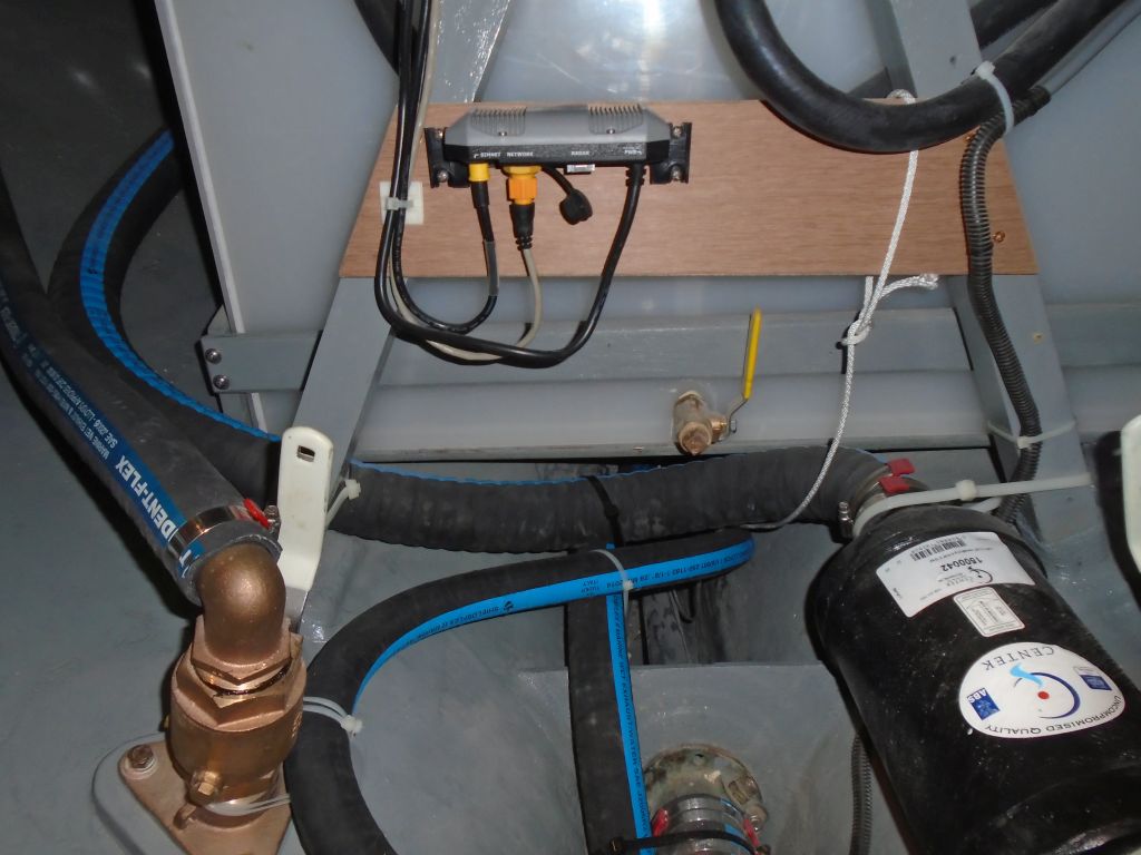
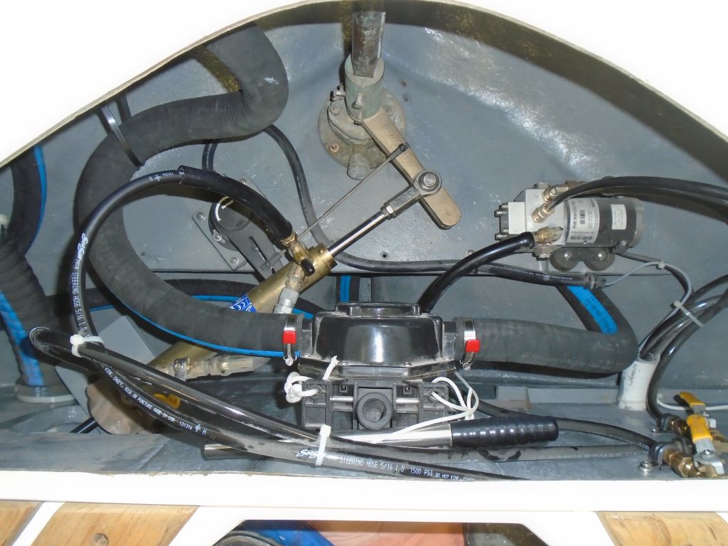
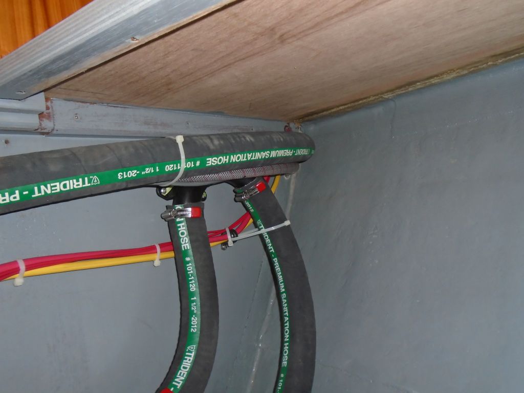
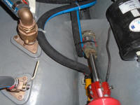
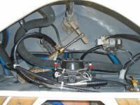
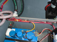
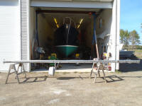
Afterwards, I made up the final length for the manual
pump's discharge. It's a busy little place back
there in what I like to call the after steering room,
but nowhere near as chaotic as these photos would make
it appear. All systems here were easily accessible
for future inspection and maintenance needs. |
 |
The biggest project of the day, in terms of basic
time-elapsed if not in difficulty or importance, was to
install the shower sump pump. When I
first installed the shower pan, with its new drain
hose led raw into the bilge pending final connection,
I'd originally thought of running it to an enclosed
submerged pump chamber somewhere in the aft bilge, but
now that the time had come to actually proceed, my
thoughts had changed, and instead I chose a stand-alone
non-submerged sump pump for the job. |
 |
During the week, as I worked on nearby projects, I'd
spent quite a bit of time contemplating the shower sump
also, and had looked into (and ultimately rejected)
several possible installation locations, including a
locker beneath the dinette (and immediately adjacent to
the head), a space at the bottom part of the starboard
storage locker, and others. Because my initial
plan had been to locate an enclosed sump chamber in the
bilge, I'd purposefully led wiring for the new pump with
this in mind, dead-ended at a terminal block in the
starboard storage locker just forward of the
galley--what used to be the hanging locker--where it
made logical sense for my vaguely-planned installation.
So this wiring lead was a factor in the pump's final
location, though certainly I could have worked with this
no matter what.
More important was the shower drain hose itself:
the new pump had to be within reach. I'd used a
long length of the 1/2" reinforced hose to give plenty
of installation flexibility, and it was likely that it
would reach anywhere I logically wanted it to, but this
was a practical consideration that, once I narrowed down
the locations, would drive the final installation more
than any other--this and the means of getting the water
overboard.
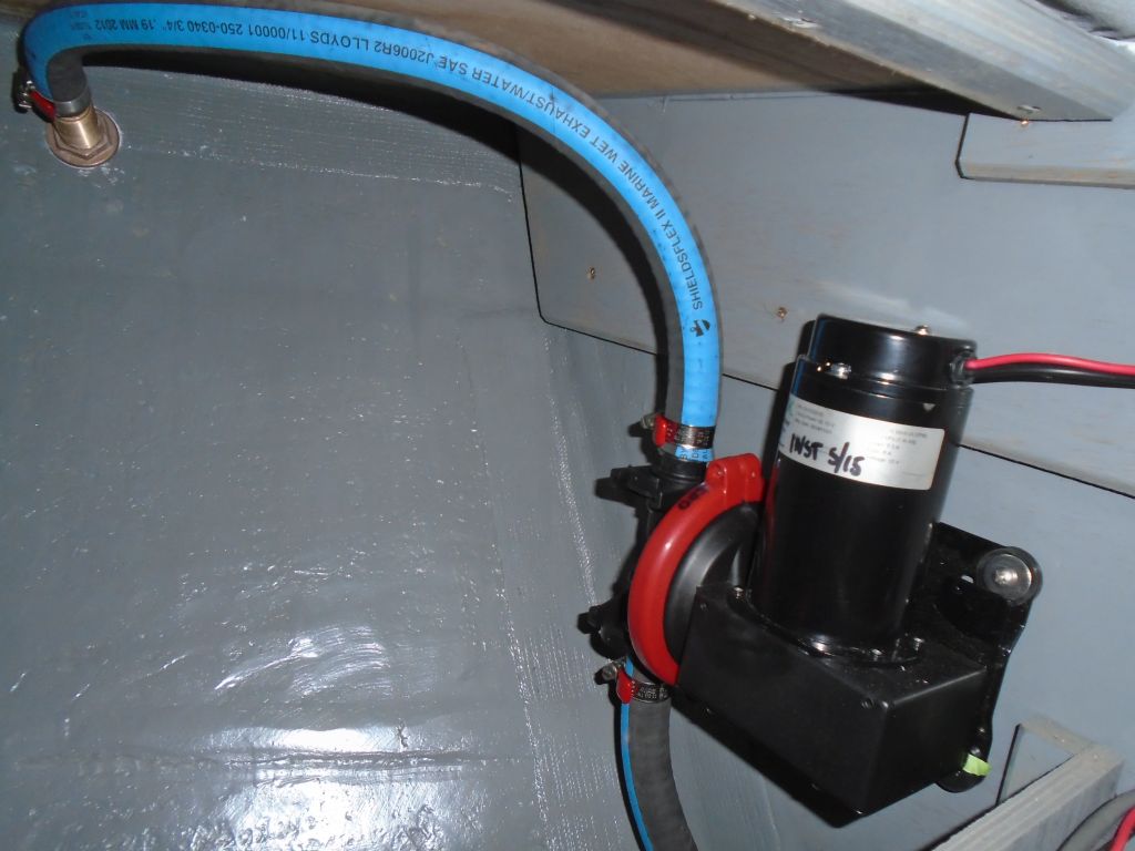
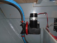
The net result of all this unspoken cogitation was that
I decided to locate the pump in the plumbing machinery
space beneath the v-berth, where the saltwater washdown
pump and septic system were also installed.
Access to the space was good, and it seemed to meet all
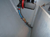
the requirements. First, though, I had to be sure
that I could lead the shower's drain hose forward to the
space, which, without much difficulty, I did: it
led nicely up the port side of the bilge and into the
open area just forward of the septic tank, where the
platform ended and the bilge was once again exposed.
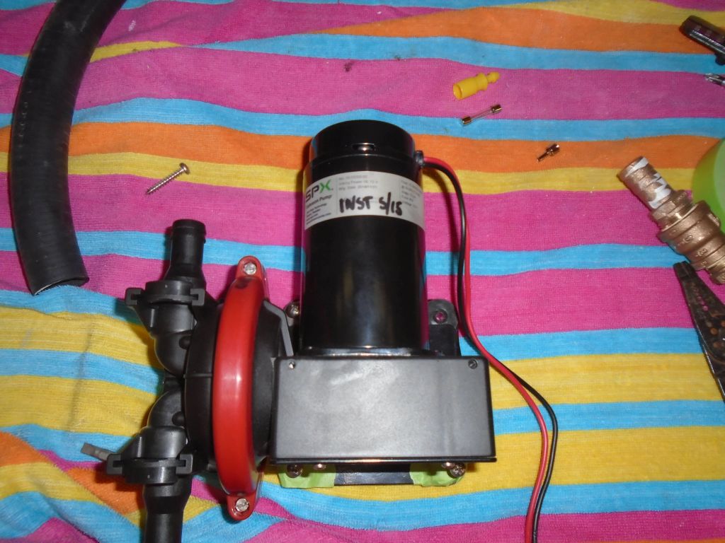
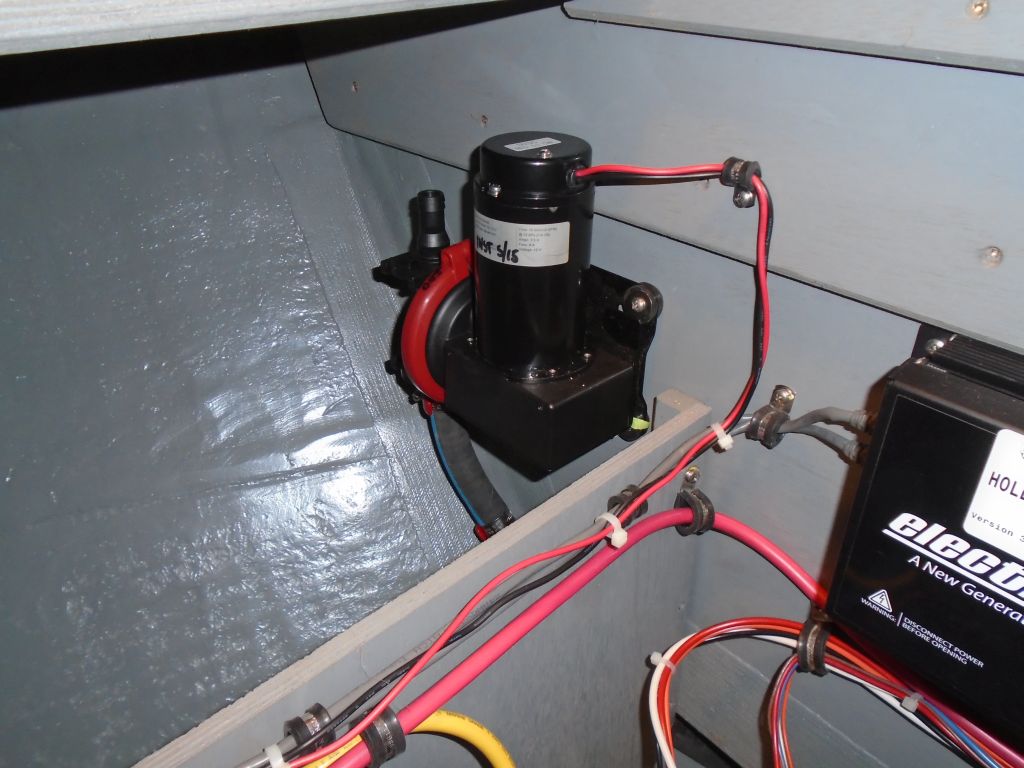
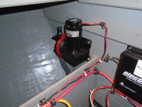
I tried out a couple possible locations within this
locker before settling on a nice area at the forward end
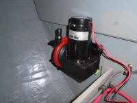
of the port side. Initial access to screw in the
pump was a little tight, and the nature of the pump base
bracket (as is so frustratingly often the case--I just
don't understand why mounting bases need be so small, as
if another 1/2" would make any difference other than to
allow for actual practical installation) was to obviate
easy installation of the fasteners and fender washers
required to secure the pump through its flexible mounts.
I had to tape the washers into place first, as they
needed to slip beneath the pump housing and couldn't be
threaded onto the screws first. |
 |
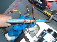
But despite this, installation went pretty easily, and
with the pump mounted I made the suction hose connection
after first adapting the 1/2" hose up to the 3/4"
required for the pump inlet, using a bronze coupling and
two bronze hose connectors of the appropriate size. |
 |
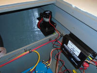
Next, I turned to the pump wiring. For this pump,
which would see intermittent use during normal practice
(as the shower pan filled up with water, a user might
choose to turn the pump on and discharge it), I elected
to provide a handy switch in the shower area. The
switch I chose had not yet arrived, but I led in the
pair of wires required to the utility space outboard of
the head, into which bulkhead I'd eventually install the
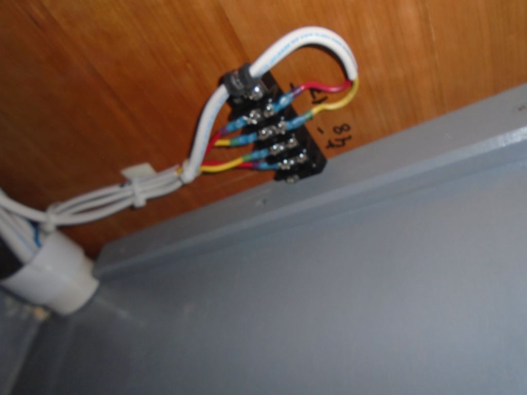
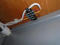
switch. Then, I made up the remaining wiring as
required, with a fuse holder in the space near the pump,
and eventually led the wires back to the terminal block
containing the remainder of the circuit leading back to
the main switch panel at the helm. |

 |
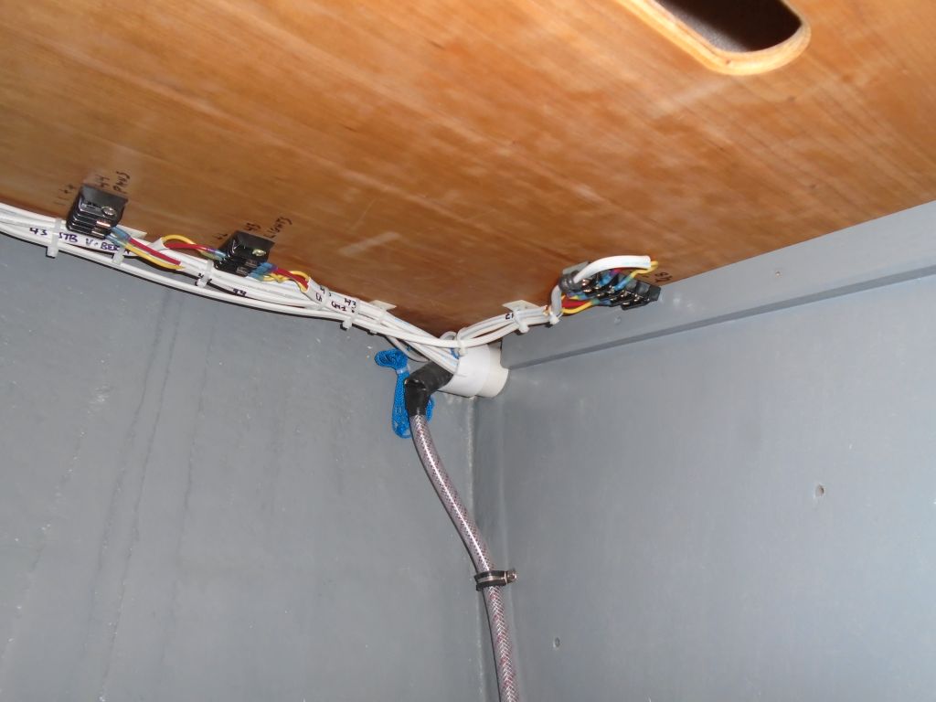
Throughout this entire process, leading back several
days, I'd also been thoughtfully considering the
location of the discharge for this pump. Once more,
hose and installation access--and logic and
practicality--ruled the day. One thought I'd had--and
the leading candidate--had been to run the hose into the
utility space outboard of the head, and install a
discharge beneath the rubrail, near the vent for the
septic tank. But I ultimately rejected this for a few
reasons. First, and foremost, I didn't think there was
room to drill another large hole through the tiny
section of bulkhead that communicated between the head
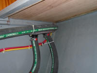
and forward cabin machinery spaces. This narrow,
V-shaped space was already chockablock with various
wires and other previously-installed hoses for the
septic system and related.
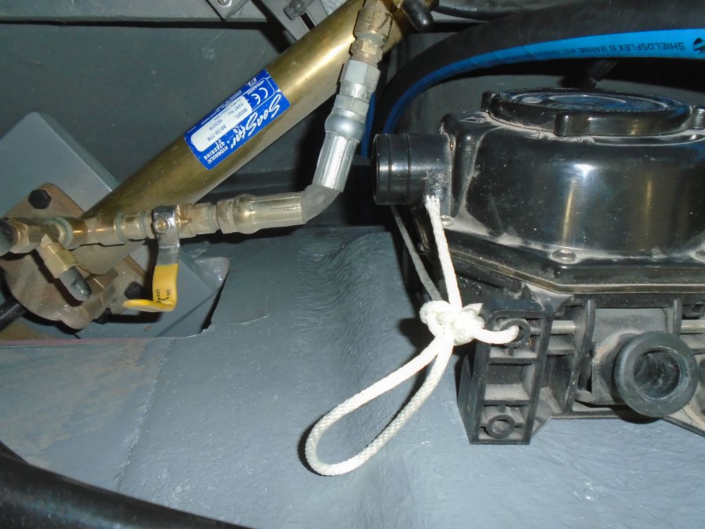
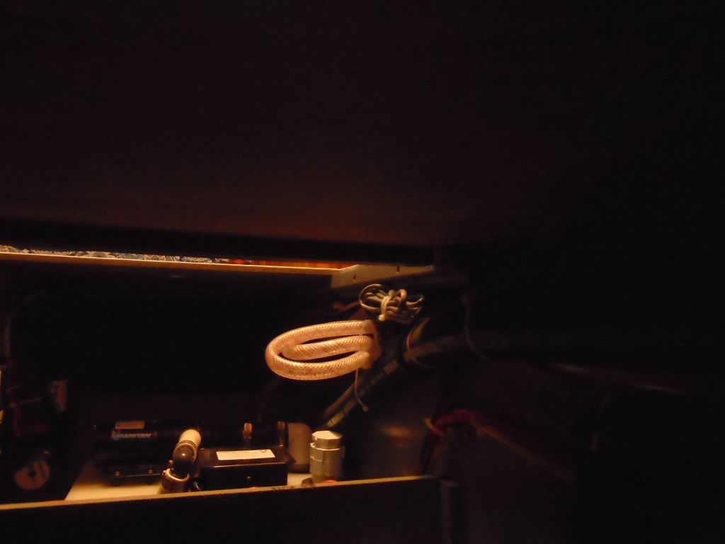
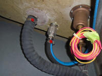
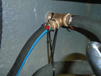
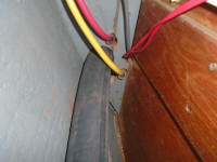
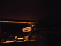
Even if space existed for another 1-1/8" hole (which I
didn't think it did), access for drilling would tough to
impossible with the existing installations, and with the
tightness of the space from the head side (photo on the
right--any new hole would have to be in that little
wedge all the way at the bottom). Note that the
two red wires on the right are the yet-to-be-finalized
wires leading to the eventual switch for this pump in
the head. |
 |
I considered other possible ways to lead in the
hose, perhaps through the bottom of the space, into the
platform where the toilet was installed, and up a tiny
hidden space at the back side of the panel, the only
such spot that communicated invisibly with the open
space beyond, but this was too complicated and
challenging, once more, to drill the access holes.
Perhaps I would have somehow made this all happen, but
for the nagging idea that I didn't like the thought of
this discharge being halfway up the hull: it would
be sure to dribble and stain, and would also be
prominent in its discharge-ness while in use.
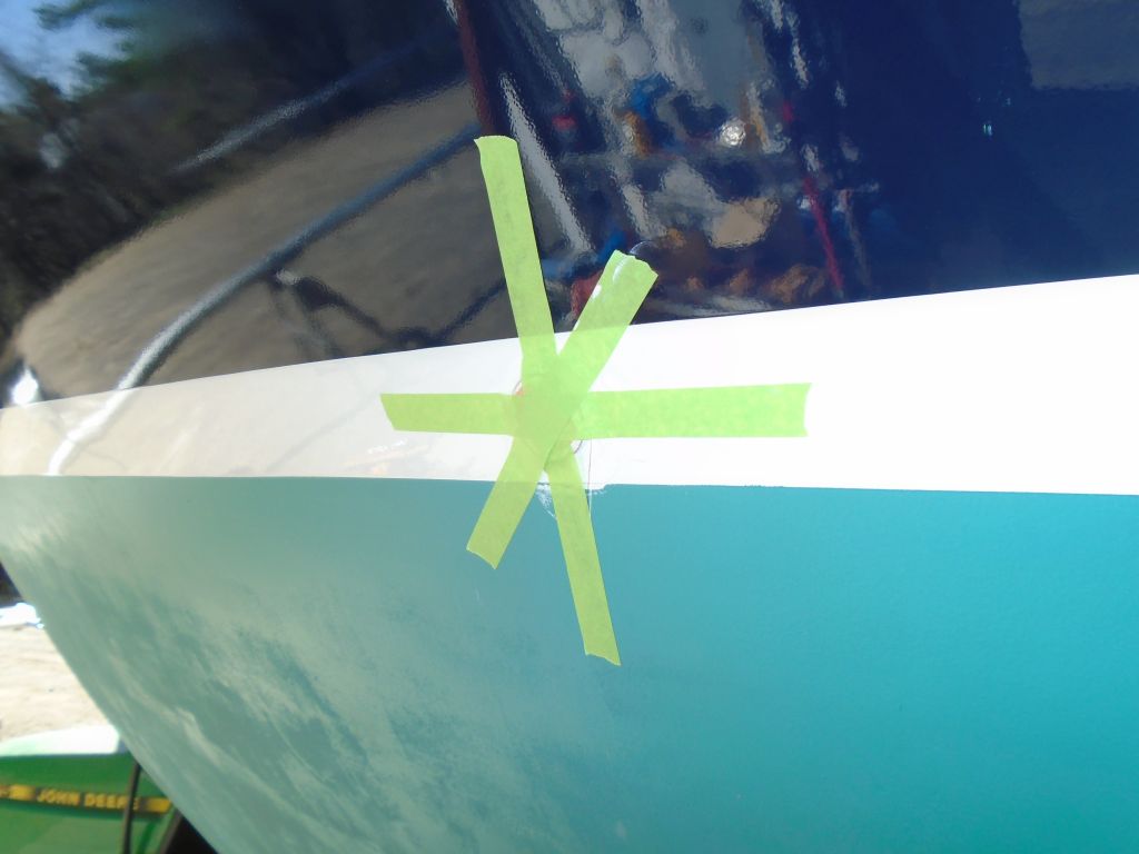
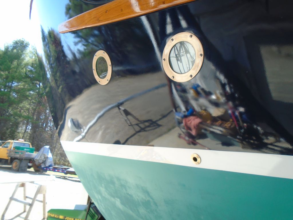
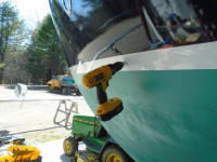
Finally, I took some measurements from outside the boat
to determine roughly where the waterline was in relation
to some known fixtures so I could translate it to inside
the hull. I measured down from the aftermost round
deadlight in the hull, which happened to be directly
above the space in which I was working, and eventually
determined that if I installed a through hull in the
boottop--well above the actual waterline, but thankfully
also beneath the top of the v-berth platform, where it
had to be in order to work. With all the
complications considered, this ended up being the best
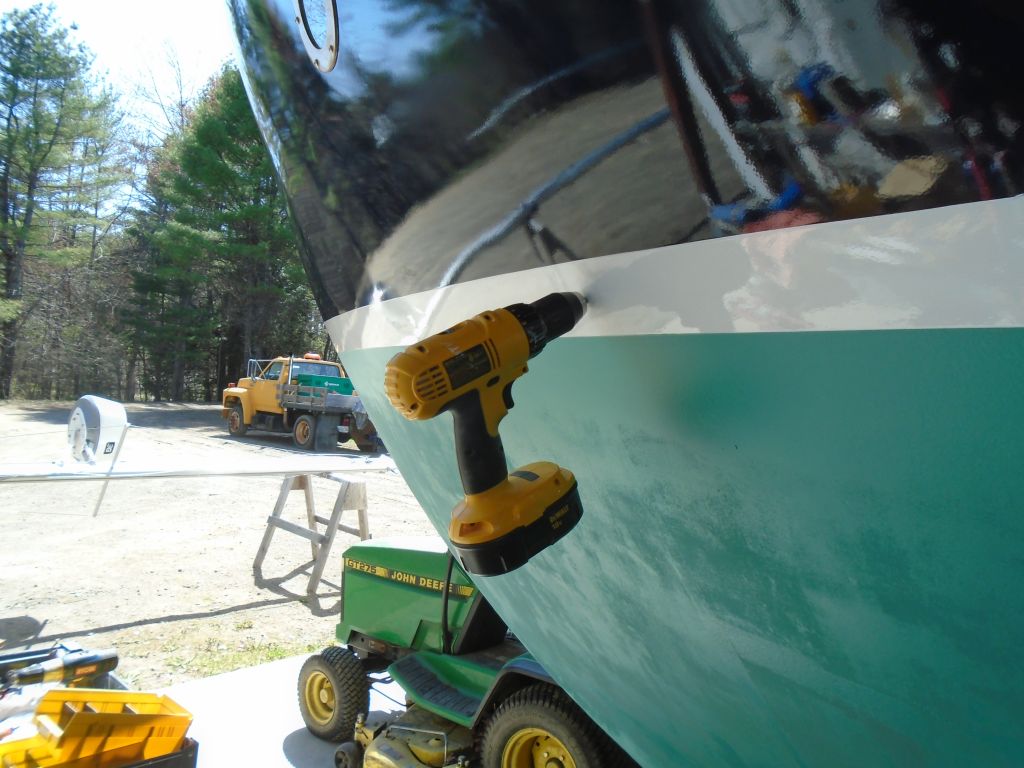
place for the discharge. To ensure my calculations
before committing to the final hole, I drilled a small
pilot hole, and from within check the location.
Perfect. Access from within was pretty easy. |
 |
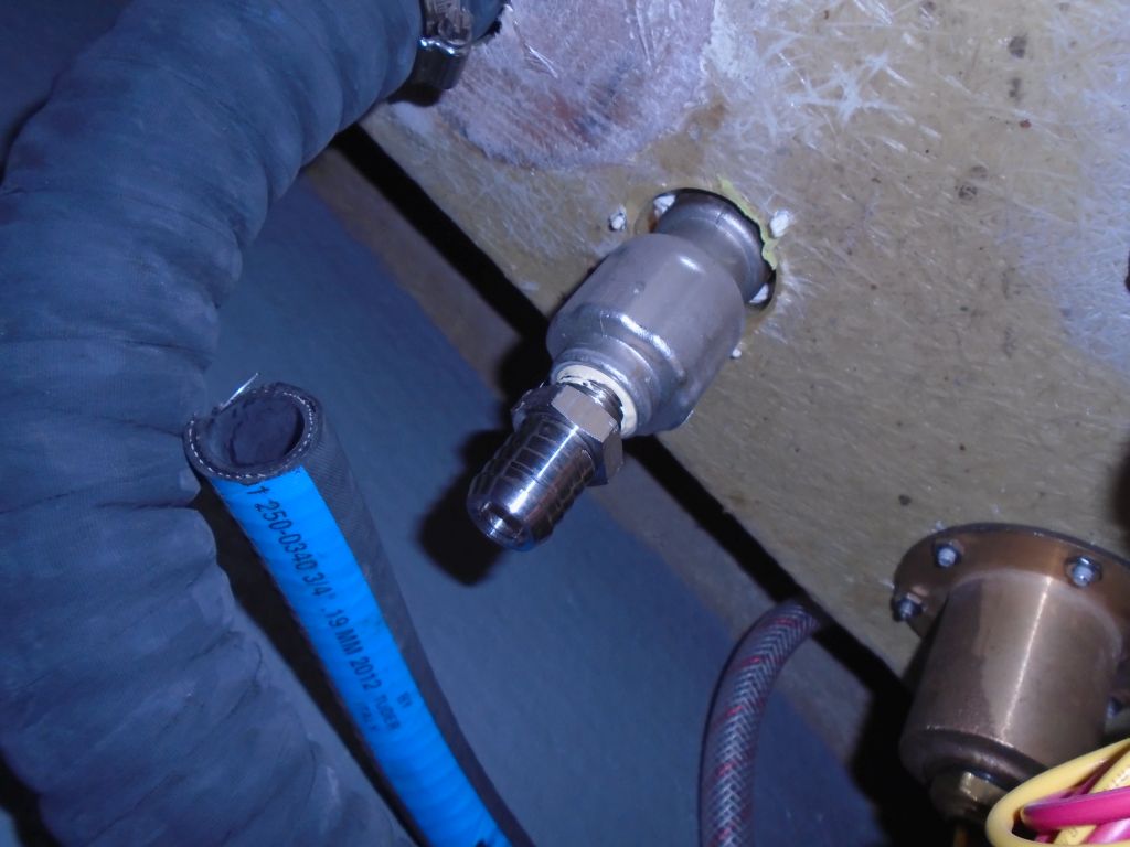
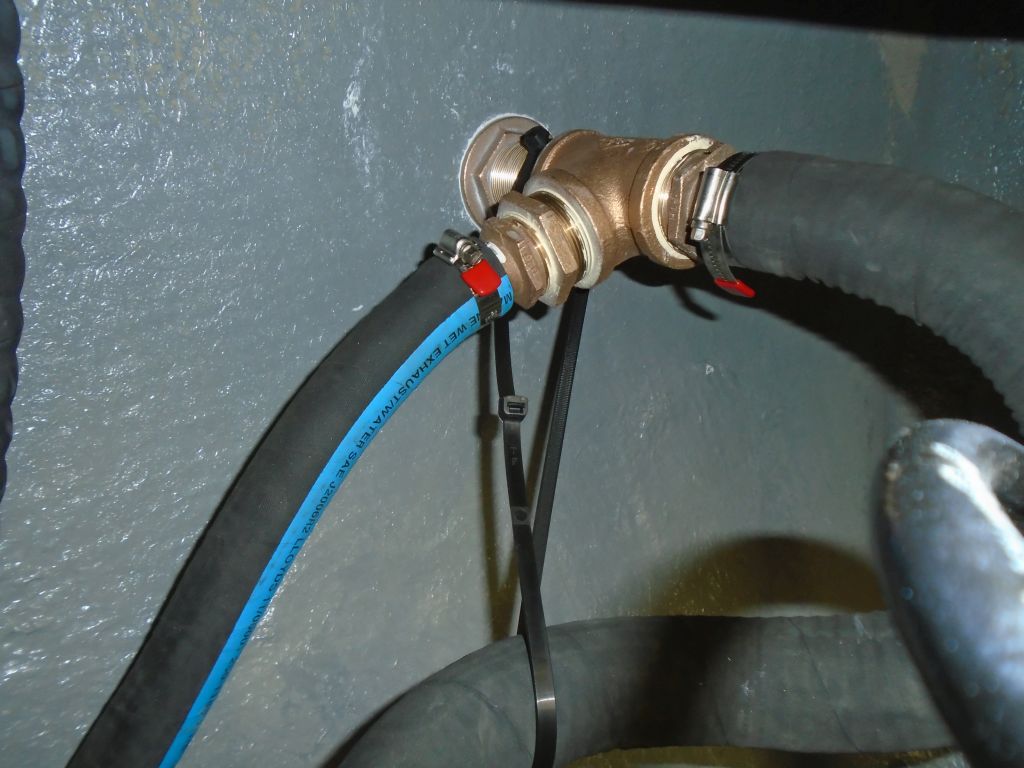
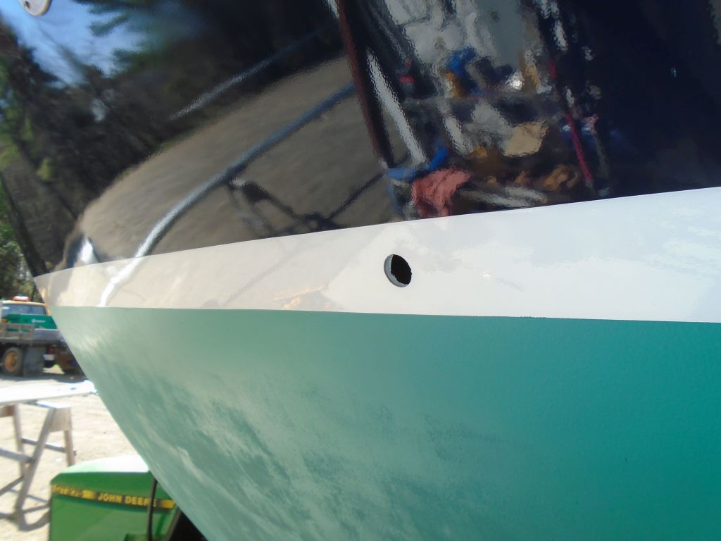
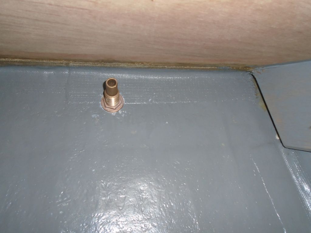
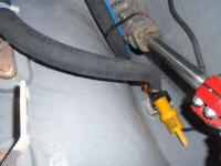
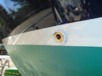
I drilled the appropriately-sized hole for the 3/4"
through hull, and even took a picture showing a view one
would never otherwise get. |

 |
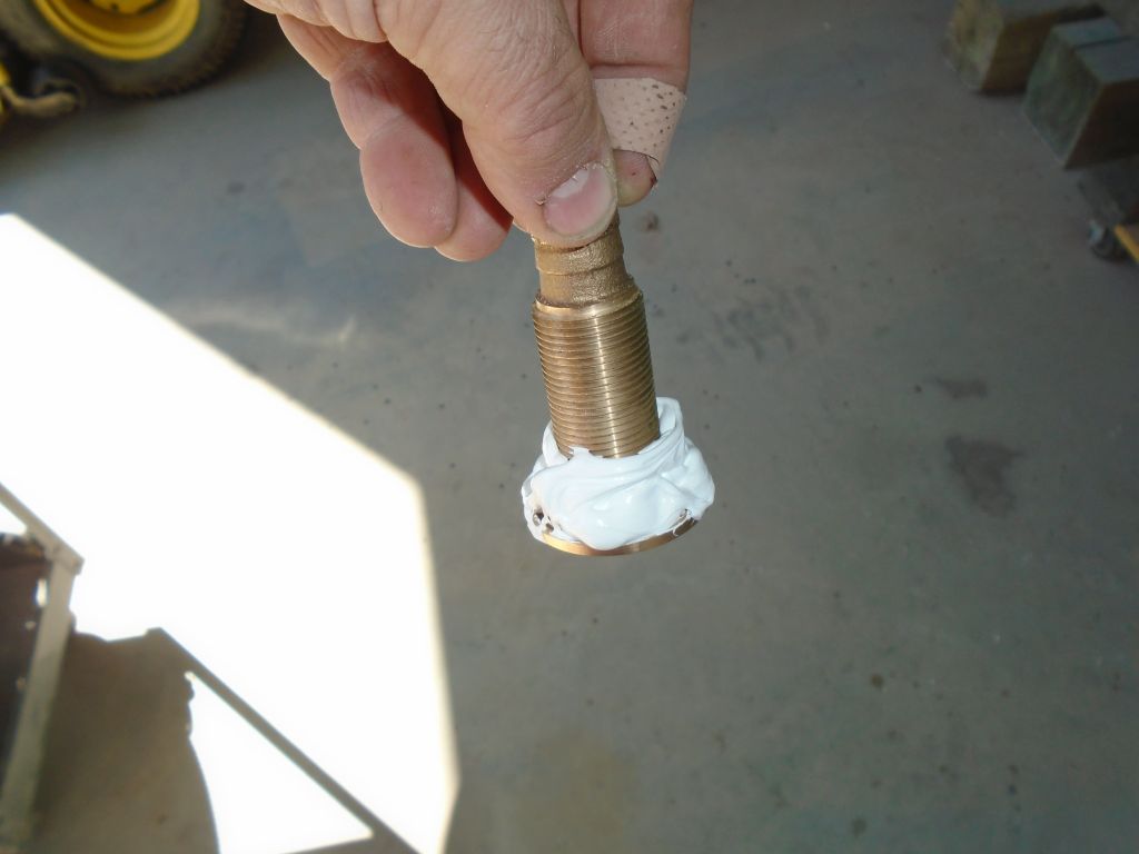
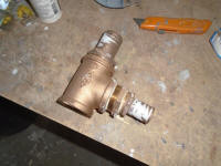
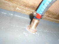
I carefully checked the through hull threads before
installation, hand-turning the nut all the way down the
shaft a couple times to make sure it would be easy to
install, after my near-disaster with the bilge pump
fitting earlier. This one worked well, so I went
ahead with the installation: lots of sealant, tape
to hold the fitting in place, and then installing the
nut from within to secure the fitting, after which I
cleaned up the excess sealant. |


 |
From there, it was simple to install the final length of
hose and clamp it securely, completing the project
(other than the switch, which was on its way after a
short backorder). |
 |
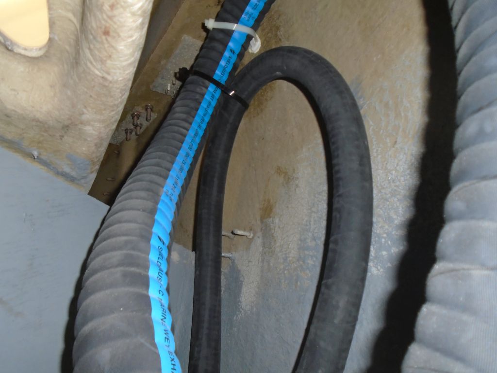
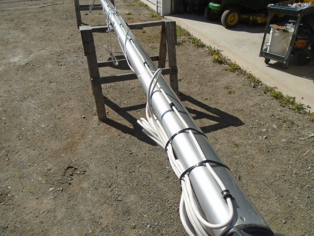
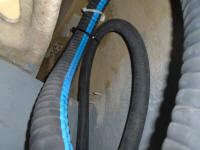
The day was drawing to a close, and rather than start
anything new and unrelated, I returned to the mizzen
mast, and completed securing the radar cable with new
clamps now on hand. |
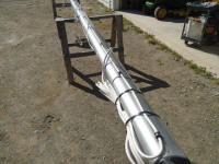 |
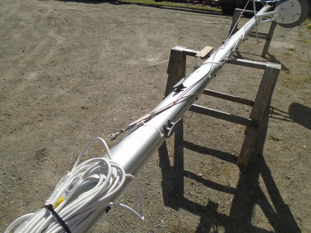
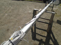
The final step for the mizzen at this point was to
reinstall various cleats and a halyard winch, all of
which I located roughly based on photos of the original
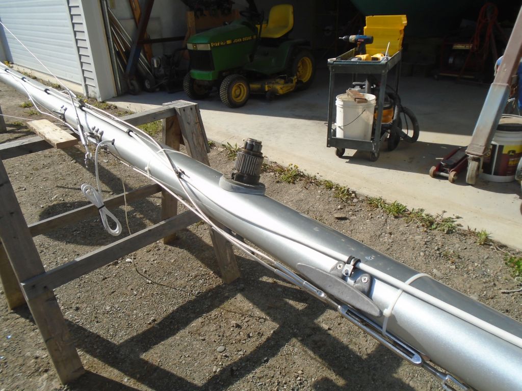
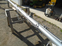
spar before I disassembled it. Repurposing an
older Barient #10 winch for the halyard (I found three
that matched; none of the winches that came off this
boat originally matched, and all were weird somehow;
fortunately I had a supply of old winches from other
boats to choose from), I mounted it on the port side of
the mast, where one had originally been, along with
three cleats--one per side, plus one on the forward side
of the mast for the mainsheet, perhaps. The winch
needed some basic servicing, as the pawls were gunked up
with inappropriate grease, but I installed it
regardless, as the servicing could occur later. I
just wanted it secured to the mast so I could wrap up
the mizzen work and move on to the mainmast shortly. |

 |
| |
Total Time Today: 7.25 Hours |
<
Previous | Next > |
|
|