Project Log: Friday, July 20, 2012
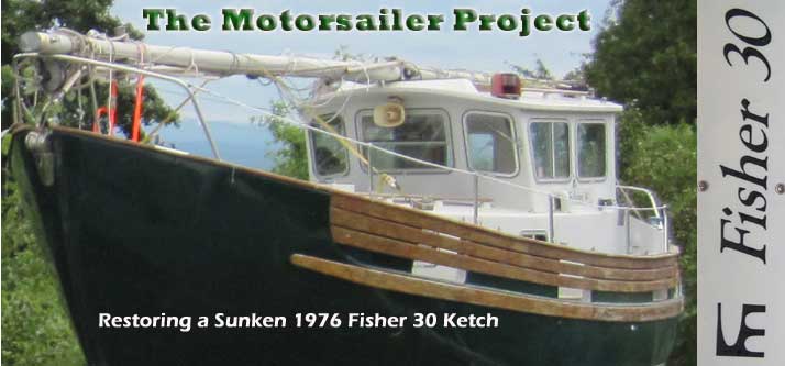
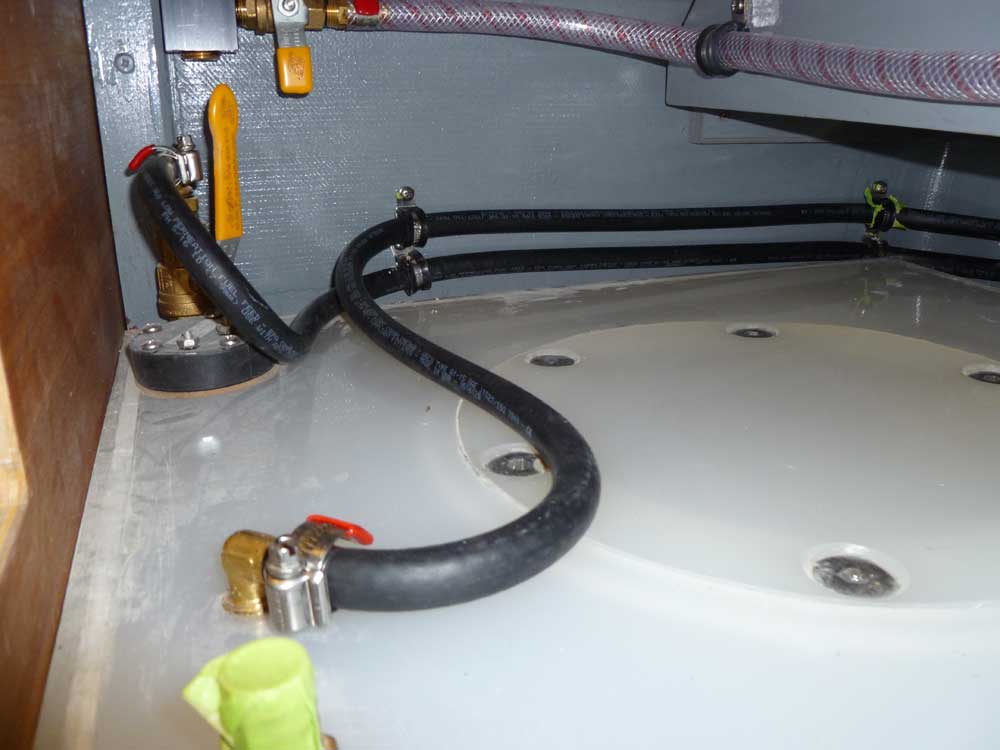
I was never a fan of doing jobs over again, but from the
moment I'd installed it I knew I'd have to redo the
several short lengths of 3/4" potable water hose that
had connected the tankage manifold to the strainer,
filter, and eventually the electric pressure pump.
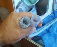
The problem with the hose was that it was just flat.
It was flat when it came out of the box (which should
have made me throw it away immediately), and it was flat
during and after installation. It wasn't just that
turning corners was kinking the hose, but even the
straight runs were oblong, and the hose walls simply
didn't seem able to support themselves. I'd noted
this during the
original
installation.
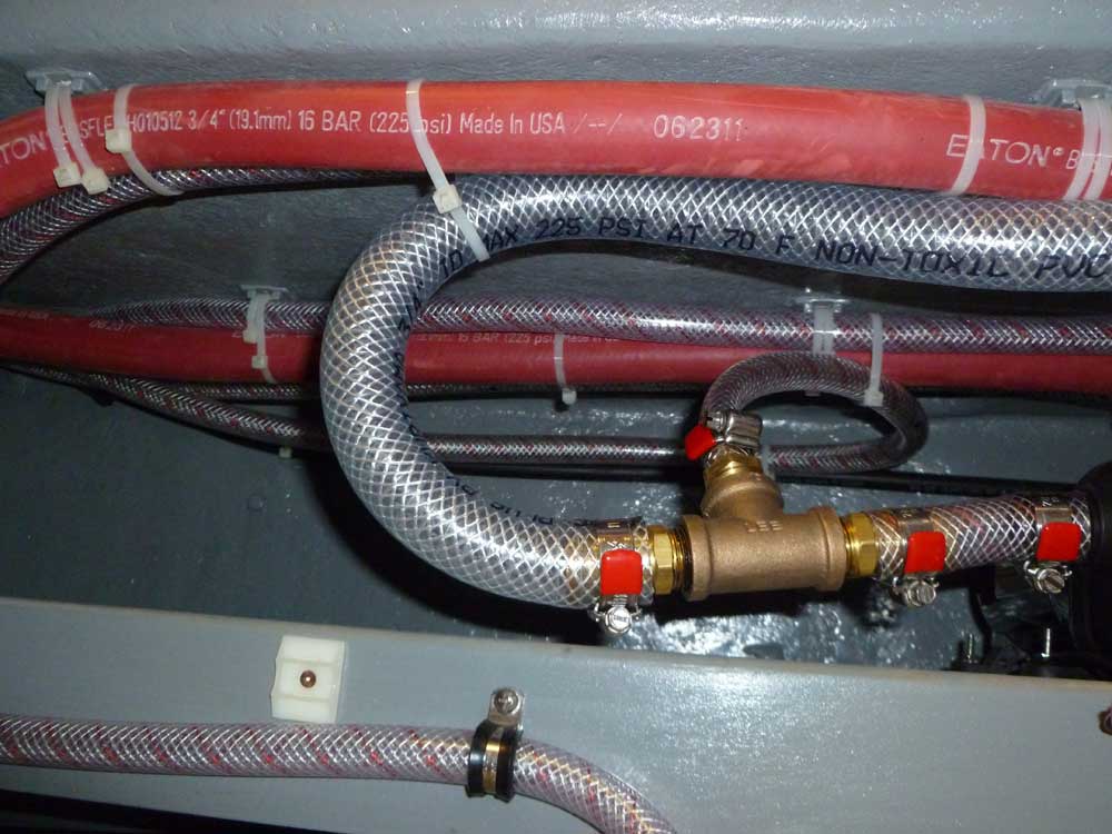
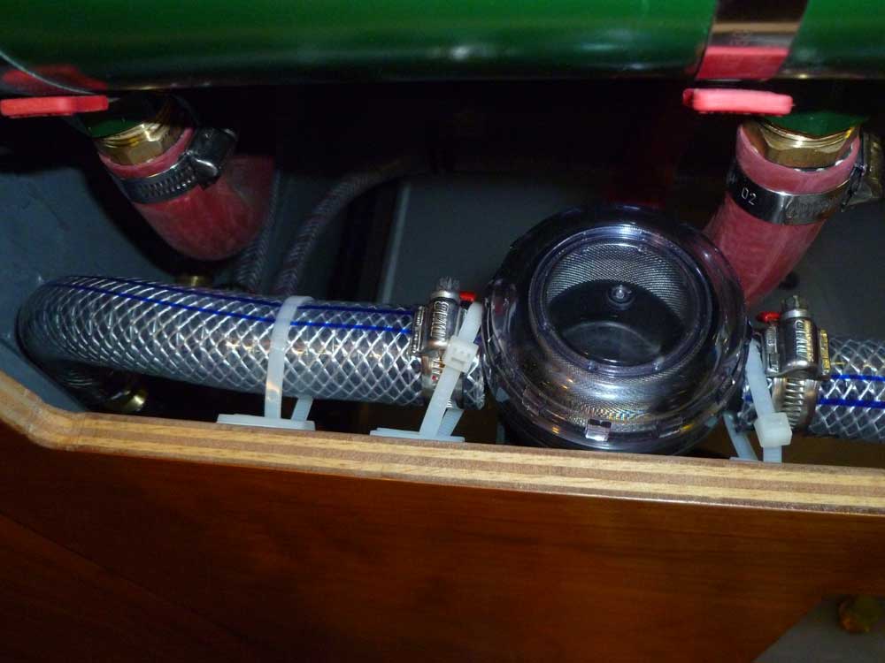
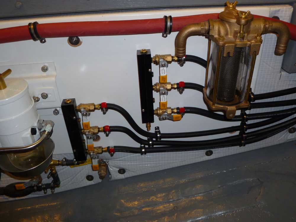
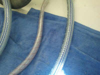
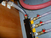
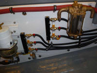
I found another type of potable water hose that had a
thicker wall, and, in addition to the normal nylon
strand reinforcement found in this type of hose, also
featured a wire helix. This hose would make
tighter bends without kinking, but most importantly it
just managed to stay round on its own. |
 |
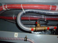
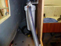
So I removed the offending hose, and replaced all
sections with the new, stiffer hose. This worked
much better, with no flattening or kinking. |
 |
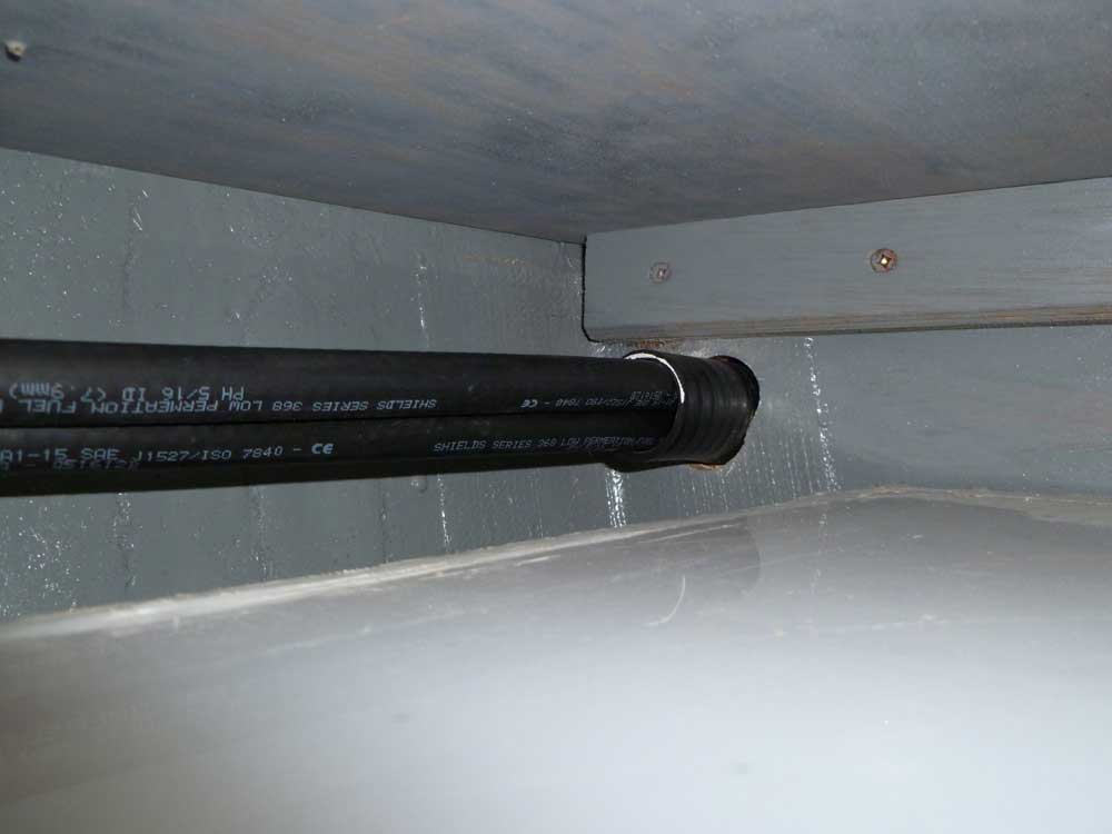
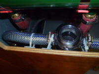
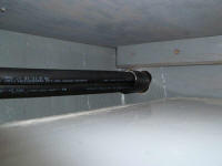
Next, I installed the fuel supply and return lines to
the center and starboard fuel tanks, completing the main
portions of the fuel system. All that remained was
to run short hoses to connect both ends of the fuel
system with the engine's supply and return connections,
but I'd wait to do that till later, since these hoses
would just be in the way short-term. |

 |
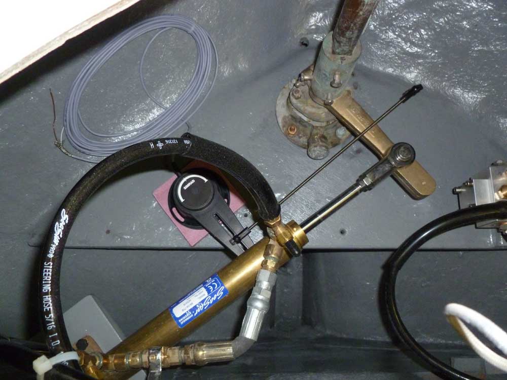
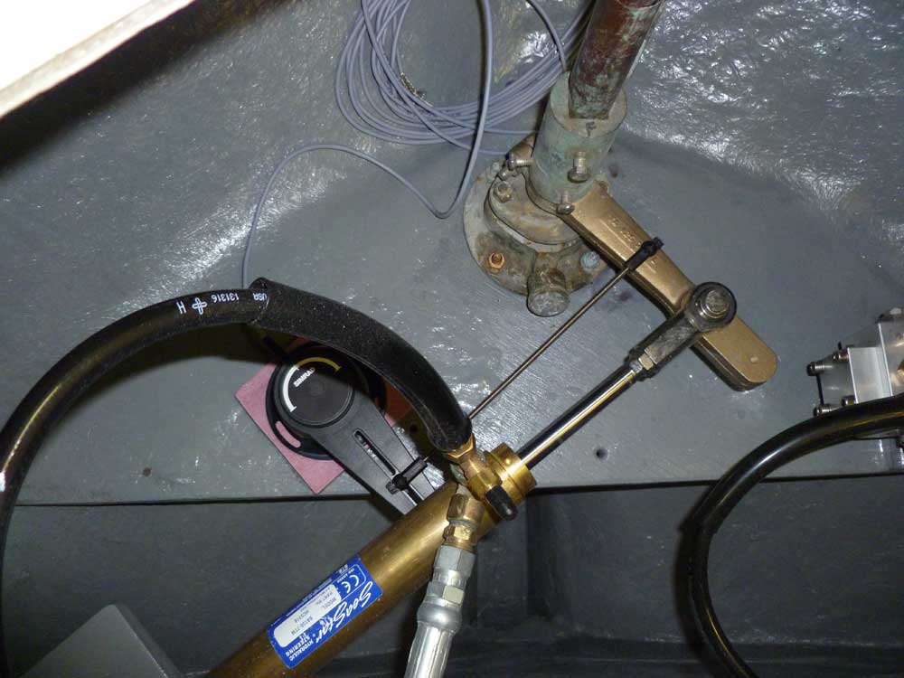
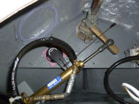
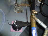
I moved on to the rudder feedback sensor for the
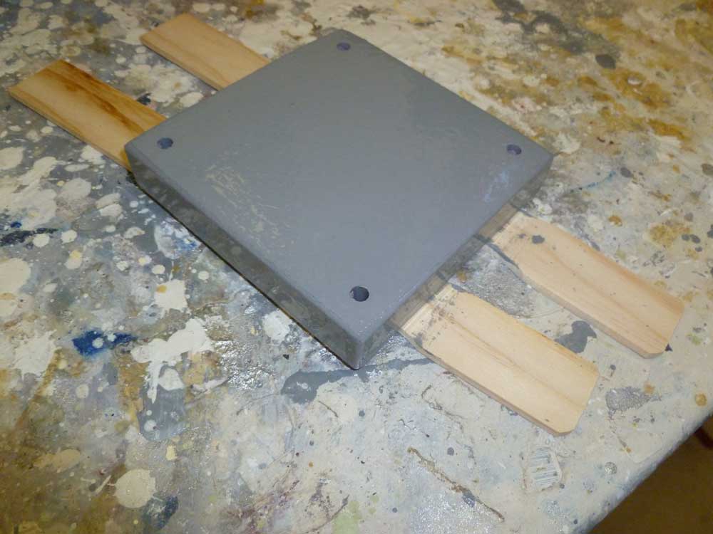
autopilot. To begin, I cut a square block from
3/4" fiberglass to support the feedback unit and bring
it even with the height of the main steering arm.
Then, I played around with the location till I found
where I wanted to mount it, with the block just at the
edge of the plywood platform that supported the rudder
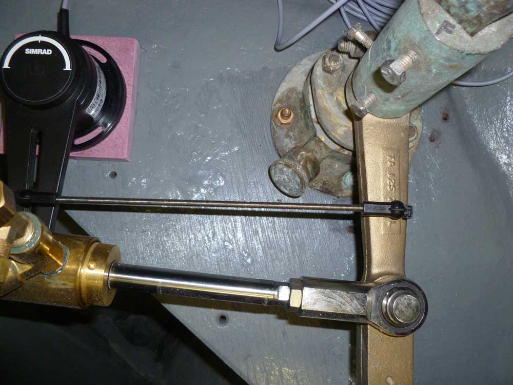
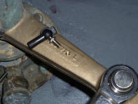
gear. Aligning the feedback unit with the
rudderpost and tiller arm as required by the
instructions, I measured and cut the excess length from
the connecting rod, a simple mechanical connection that
just turned the feedback arm in direct accordance with
the rudder's movement.
|
 |
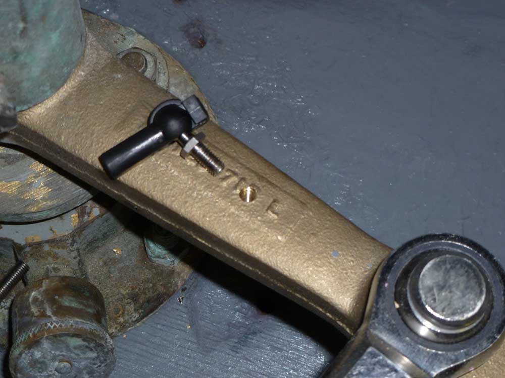
After marking the center of the connecting rod's
attachment point, I drilled and tapped the bronze rudder
arm for the mounting stud, using a drill and tap bought
just for this purpose (and which I'd likely never use
again). |
 |
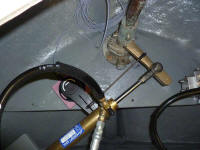
Then, I dry-fit all the components to check the
orientation, and swung the rudder through its arc from
side to side to check for binding or other issues.
I'd do this again before final installation. While
the connecting rod was aligned perpendicular to the
center of the rudder arm, the designed position of the
steering cylinder (slightly offset when the rudder is
centered) makes it look like something's misaligned, but
this is not the case. |
 |
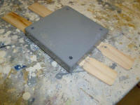
To prepare for final installation, I applied a coat of
gray paint to the new support block so I could install
these components in the near future. |
 |
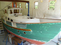
Some garage door maintenance earlier in the week had
given me an opportunity for a different perspective of
the boat while up a ladder at the front of the shop, so
I brought up a camera. |
 |
| |
Total Time Today: 4.75 hours
|
<
Previous | Next > |
|
|